Rockwell Automation 1794-ID2/B INSTALL INSTR 24v FLEX I/O 2 CHANNEL Incremental Encoder Module User Manual
Page 13
FLEX I/O 2-Channel Incremental Encoder Module 13
Publication 1794-IN063C-EN-E - February 2014
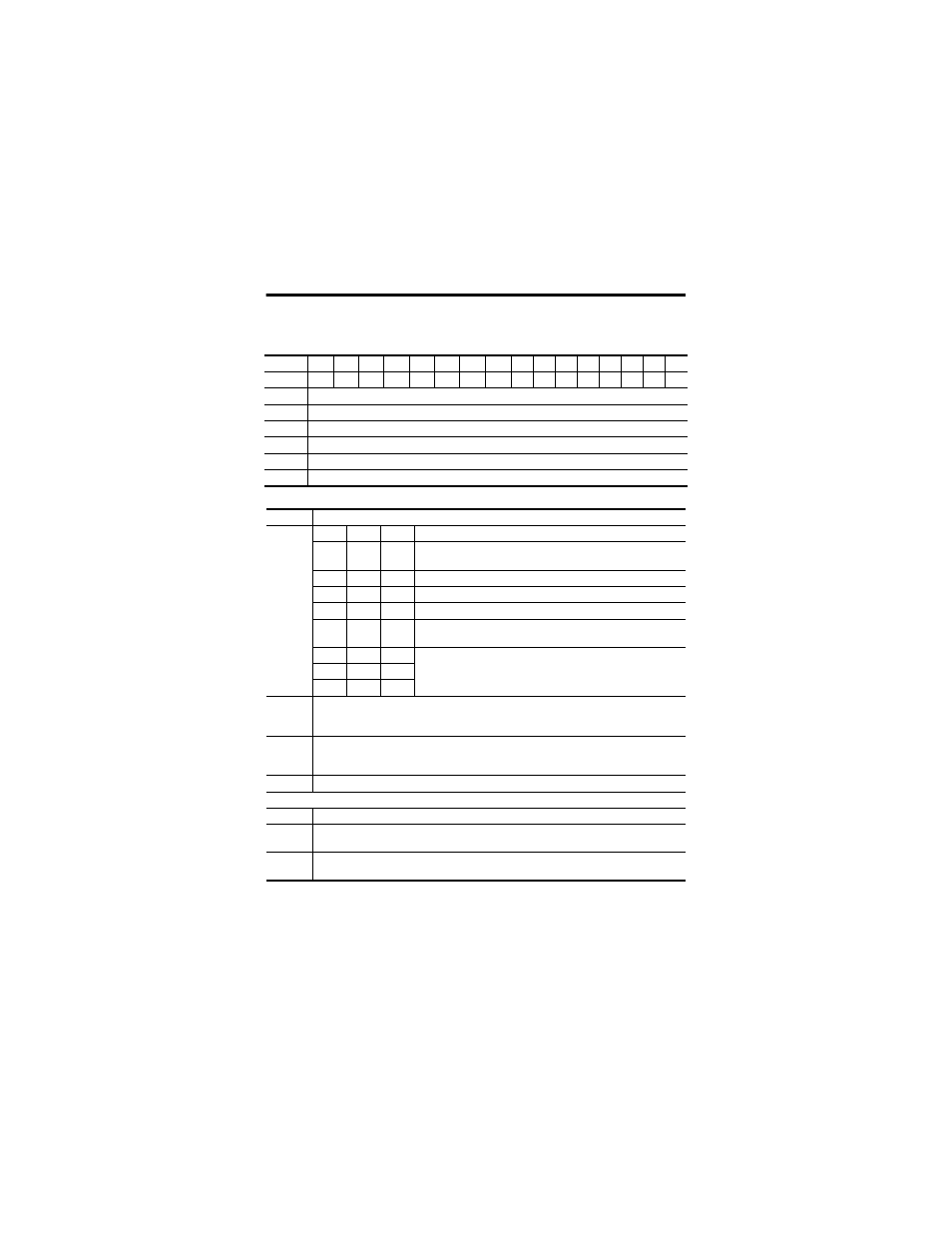
Output/Configuration Image for 1794-ID2
Dec.
15
14
13
12
11
10
9
8
7
6
5
4
3
2
1
0
Oct.
17
16
15
14
13
12
11
10
7
6
5
4
3
2
1
0
0
Control Word 0 - Channel 0 - Sets the function of counter 0
1
Control Word 1 - Channel 1 - Sets the function of counter 1
2
Channel 0 Preset - Value to load or compare with counter 0
3
Channel 1 Preset - Value to load or compare with counter 1
4
Control Word 2 - Filter Function Control Word - Enables filter, and sets filter constant
5…6
Reserved
Description of Control Words 0 and 1
Bit
Description
00…02
02
01
00
Mode Selection Bits
0
0
0
Counting on positive (rising) edge of input signal A. (Up/dwn
counting determined by B.)
0
0
1
Quadrature encoder X1
0
1
0
Quadrature encoder X2
0
1
1
Quadrature encoder X4
1
0
0
Counting up on positive edge of input signal A, and counting
down on positive edge of input signal B.
1
0
1
No count function
1
1
0
1
1
1
03
Preset (Reset) bit - A positive edge on this bit moves the value in Preset X to
Counter X, independent of Preset Enable. Note: To use Preset as a Reset, use a count
value of 0000 in the Preset Value word.
04
Enable Z Preset (Reset) bit - When this bit is set (1), a positive edge on Z preloads
Counter X = Preset X, independent of Cal Enable. Note: If Z is configured to do Store
and Preset (Reset), the Store will occur first.
05
Count Enable bit - When this bit is set (1), the pulse counter is enabled.
Calibration Control Bits 06-08
06
Enable bit - When this bit is set (1), the pulse counter can be calibrated.
07
Direction bit - When this bit is set (1), calibration is performed in a negative
direction; when reset (0), calibration is performed in a positive direction.
08
Reset bit - Calibration is acknowledged and a new calibration is enabled on a
positive edge on this bit.