Input delay times – Rockwell Automation 1793-IB4S FLEX INTEGRA 4 INPUT MODULE User Manual
Page 6
6
FLEX Integra 4 Input Module
Publication 1793-5.1 - September 1999
Memory Mapping
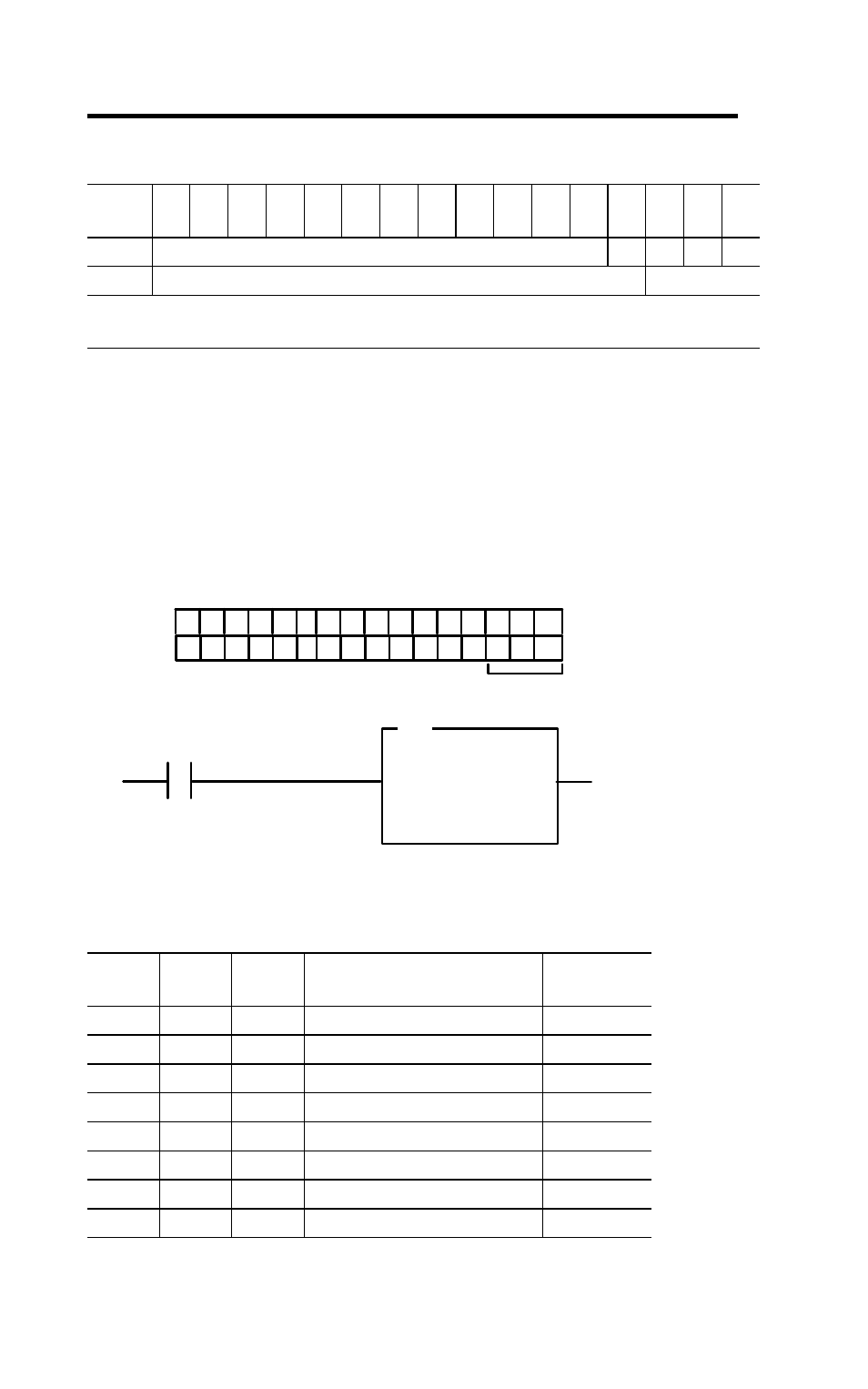
Setting the Input Delay Time
You can select the input delay time (DT) for channels 00 thru 03. Select the
input delay time by setting the corresponding bits in the output image table
(complementary word) for the module.
For example, to set a delay time of 4ms for an input module at address rack
1, module group 0, set bits 02, 01 and 00 as shown below.
Input Delay Times
Bit/
Word
15
14
13
12
11
10
09
08
07
06
05
04
03
02
01
00
Read
Reserved
I3
I2
I1
I0
Write
Reserved
DT 00-03
Where: I = Input
DT = delay time - refer to “Setting the Input Delay Time”
02
01
00
Filter Time for Inputs 00-03
Selected
Filter Time
0
0
0
Filter Time 0 (default)
512
μs
0
0
1
Filter Time 1
1ms
0
1
0
Filter Time 2
2ms
0
1
1
Filter Time 3
4ms
1
0
0
Filter Time 4
8ms
1
0
1
Filter Time 5
16ms
1
1
0
Filter Time 6
32ms
1
1
1
Filter Time 7
64ms
15 14 13 12
11 10 09 08 07 06 05 04 03 02 01 00
0
1
1
= 3 Octal or 3 decimal
Write delay time on system startup.
Write DT to complement
of input module.
Fill File
Source
Destination
Length
3
#O:010
1
I:000
00
FLL
O:010
Dec.
41335