Wiring – Rockwell Automation 1793-IB4S FLEX INTEGRA 4 INPUT MODULE User Manual
Page 4
4
FLEX Integra 4 Input Module
Publication 1793-5.1 - September 1999
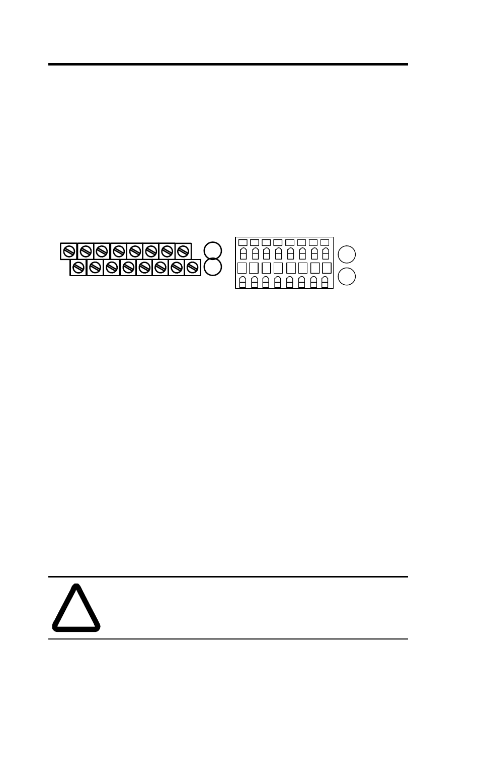
Wiring
This module is available with 2 styles of terminations: 1793-IB4 -
screw-cage and 1793-IB4S - spring-clamp. Refer to the wiring figure
below.
1.
Connect individual sensor signal input leads to terminals 2 through 5
on row A (channels 0 thru 3 respectively).
2.
Connect sensor supply lead to +24V dc (terminals 1, 6, 9, or 14).
(Terminals 1, 6, 8, 9, 14 and 15 are connected internally to +24V dc.)
3.
For 3-wire sensors only: Connect associated common to terminals 10
through 13 on row B.
4.
Connect +24V dc voltage to terminal 8 on row B.
5.
Connect 24V dc common to terminal 0 on row A.
6.
If daisy-chaining + voltage from this module to the next Integra
module, connect a jumper from terminal 15 to terminal 8 on the next
FLEX Integra module.
7.
If daisy-chaining 24V dc common from this module to the next FLEX
Integra module, connect a jumper from terminal 7 on this module to
terminal 0 on the next Integra module.
.
!
ATTENTION:
Total current draw through the module’s
(+) voltage terminals is limited to 10A. Separate power
connections to the module may be required.
0
1
2
3
4
5
6
7
8
9
10
11
A
B
13
14
15
12
41378
C
V I
I
I
I
C
V
C
C
V
V
C
C
V
V
Ch 0
Ch 1
Ch 2 Ch 3
0
1 2 3 4 5 6
7
8 9 10 11 12 13 14 15
A
B
41379
C V I
I
I I
C
V
C C
V
V
C C
V
V
Ch 0 Ch 1 Ch 2 Ch 3
1793-IB4
1793-IB4S
Where: C = common, V = +24V dc power, I = input