Rockwell Automation 1794-ADN/C, 1794-ADNK/C FLEX I/O DeviceNet Adapter Module Installation Instructions User Manual
Page 3
3
Publication 1794-IN099C-EN-P - May 2010
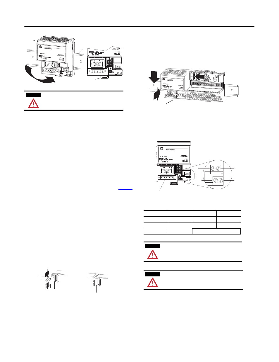
Mounting on a DIN rail before installing the Terminal Base Units
1. Position the DeviceNet adapter module (A) on an IEC standard,
(35 x 7.5 x 1 mm) top-hat DIN rail (B), at a slight angle.
2. Hook the lip on the rear of the adapter onto the top of the DIN
rail, and rotate the adapter onto the rail.
3. Press the adapter module down onto the DIN rail until flush.
Locking tab C will snap into position and lock the adapter to the
DIN rail.
4. If the adapter does not lock in place, use a screwdriver or similar
device to move the locking tab down while pressing the adapter
flush onto the DIN rail, and release the locking tab to lock the
adapter in place. If necessary, push up on the locking tab to lock.
5. Connect the adapter wiring as shown under “Connecting Wiring”
later in this document.
Panel/Wall Mounting
If mounting this adapter to a panel or wall, refer to publication
1794-2.13
.
Mounting (or Replacing) the Adapter on an Existing System
1. Remove the DeviceNet plug-in connector from the front of the
adapter.
2. Disconnect any wiring jumpered to the adjacent terminal base.
3. Open the module latching mechanism and remove the module
from the base unit to which the adapter will be attached.
4. Push the flexbus connector toward the right side of the terminal
base to unplug the backplane connection.
5. Release the locking tab and remove the adapter module.
6. Before installing the new adapter, notice the notch on the right
rear of the adapter. This notch accepts the hook on the terminal
base unit. The notch is open at the bottom. The hook and adjacent
connection point keep the terminal base and the adapter tight
together, reducing the possibility of a break in communication
over the backplane.
7. Complete the adapter mounting as shown below.
Push down and in at the same time to lock the adapter to the DIN
rail.
If the adapter does not lock in place, use a screwdriver or similar
device to move the locking tab down while pressing the adapter
flush onto the DIN rail, and release the locking tab to lock the
adapter module in place. If necessary, push up on the locking tab
to lock.
When the adapter is locked onto the DIN rail, gently push the
flexbus connector into the adapter to complete the backplane
8. Reinstall the module in the adjacent terminal base unit.
9. Reconnect adapter wiring as described in “Connecting Wiring.)
Connect Wiring
1. Connect the DeviceNet cable to the removable connector as
shown.
2. Insert connector into mating connector on the DeviceNet adapter
module.
ATTENTION
During mounting of all devices, be sure that all debris (metal chips,
wire strands, etc.) is kept from falling into the module. Debris that
falls into the module could cause damage on power up.
B
C
A
44977
44978
Connect To
BLK wire
-V
WHT wire
CAN high
BLU wire
CAN* low
RED wire
+V
Bare wire
Drain
* CAN = Controller Area Network
ATTENTION
When connecting wiring, torque terminal screws D, E, F and G to
0.8 Nm (7 lb-in).
ATTENTION
Do not wire more than 2 conductors on any single terminal.
C
44979
D
G
E
24V
COM
DeviceNet Connector
F
44980