Input wiring, 8compact™ 240v ac input module, Basic wiring – Rockwell Automation 1769-IM12 Compact 1769-IM12 240Vdc Input Module User Manual
Page 8
8
Compact™ 240V ac Input Module
Publication 1769-IN011B-EN-P
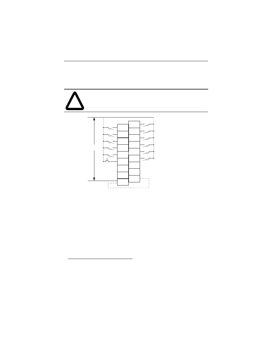
Input Wiring
Basic wiring
1
of input devices to the 1769-IM12 is shown below.
A removable, write-on label is provided with the module. Remove the label from
the door, mark the identification of each terminal with permanent ink, and slide
the label back into the door. Your markings (ID tag) will be visible when the
module door is closed.
1.A current limiting resistor can be used to limit inrush current; however, the operating
characteristics of the ac input circuit will be affected. If a 15K W resistor is placed in series
with the input, the inrush current is reduced to 35 mA. In this configuration the minimum
on-state voltage increases to 176V ac.
Before adding the resistor in a hazardous environment, be sure to consider the operating
temperature of the resistor and the temperature limits of the environment. The operating
temperature of the resistor must remain below the temperature limit of the environment.
!
ATTENTION: Be careful when stripping wires. Wire fragments
that fall into a module could cause damage at power up. Once
wiring is complete, ensure the module is free of all metal
fragments.
IN 7
IN 5
IN 3
IN 1
AC
COM
IN 6
IN 4
IN 2
IN 0
L1
L2
200/240V ac
NC
NC
IN 10
IN 8
AC
COM
NC
NC
IN 11
IN 9
Commons are
connected internally.
Note: Do not use
the NC terminals
as connection