Rockwell Automation 1746-NI16V SLC 500 Analog I/O Modules User Manual
Page 14
14 SLC 500™ Analog Input Modules
Publication 1746-IN001B-US-P
Wiring Input Devices to the 1746-NI16
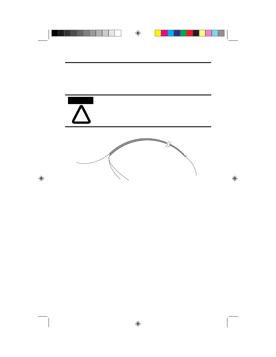
After the analog input module is properly installed in the chassis, follow the wiring
procedure below using Belden 8761 cable.
To wire your 1746-NI16 module follow these steps.
1. At each end of the cable, strip some casing to expose the individual wires.
2. Trim the signal wires to 50 mm (2 inch) lengths. Strip about 5 mm
(3/16 inch) of insulation away to expose the end of the wire.
3. At one end of the cable, twist the drain wire and foil shield together.
4. At the other end of the cable, cut the drain wire and foil shield back to the cable.
5. Connect the signal wires to the 1746-NI16 terminal block or interposing
terminal block.
6. Connect the shield drain wire to chassis ground.
7. Connect the other end of the cable to the voltage or current transmitter terminals.
8. Repeat steps 1 through 7 for each channel on the module.
!
ATTENTION
Care should be taken to avoid connecting a voltage source to a
current input module. Improper module operation or damage to
the voltage source can occur.
Cable
(Cut foil shield and
drain wire.)
Signal Wire
Foil Shield
Drain Wire
Signal Wire
(Twist the drain wire and the foil shield together and connect to earth ground or to the chassis
mounting screws.)
@JO#VTQQE
@JO#VTQQE
".
".