Wiring single-ended inputs – Rockwell Automation 1746-NI16V SLC 500 Analog I/O Modules User Manual
Page 10
10 SLC 500™ Analog Input Modules
Publication 1746-IN001B-US-P
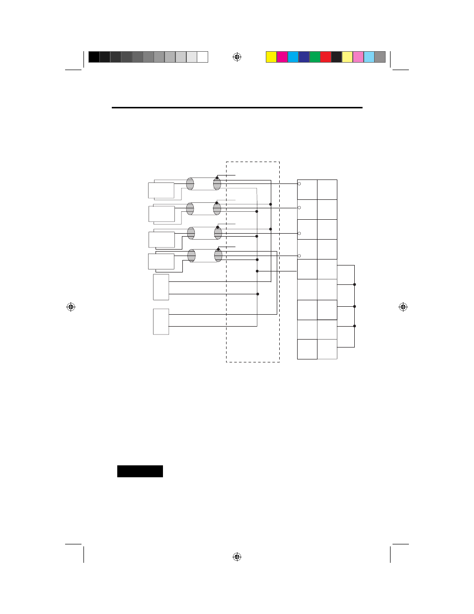
Wiring Single-Ended Inputs
The diagram below shows typical wiring for the 1746-NI16V module.
(1) There are two common terminals for all of the 16 voltage inputs. These two analog common terminals are
connected internally.
(2) All shield wires should be connected to chassis mounting screws.
(3) Unused channels should be connected to the analog common terminals (0 Volts).
(4) If separate shielded cables are used for each analog input channel, interposing terminal blocks are needed
to terminate up to 16 common wires. Then 1 to 4 common wires should be wired from the interposing
terminal block to the 2 common terminals on the 1746-NI16V module.
(5) The module does not provide loop power for analog inputs. Use a power supply that matches the transmitter
specifications.
(6) More than one power supply can be used if all supplies are class 2.
NOTE
Although the above diagram has 12 unused inputs, only 4
channels are shown connected to the Analog Com as an
example.
+
+
+
+
-
IN0
IN1
IN3
IN2
IN4
IN5
IN7
IN6
Analog
Com
Analog
Com
IN9
IN8
IN10
IN11
IN13
IN12
IN14
IN15
+
-
+
-
+
-
+
-
+
+
-
-
Channel 0
Voltage
Transmitter
Channel 2
Voltage
Transmitter
Channel 4
Voltage
Transmitter
Channel 6
Voltage
Transmitter
(2)
(3)
(3)
(3)
(3)
(2)
(2)
(2)
(4)
Vdc
power supply
(5)
Optional second
Vdc power
supply
(6)
(1)
(1)
@JO#VTQQE
@JO#VTQQE
".
".