Groundthe module – Rockwell Automation 1771-CFM Config. Flowmeter Installation Instructions User Manual
Page 11
Configurable Flowmeter Module
11
Publication 1771ĆIN043B-EN-P - July 2002
When using shielded cable wire, ground the foil shield and
drain wire only at one end ofthe cable. We recommend that
you wrap the foil shield and drain wire together and connect
them to a chassis mounting bolt. At the opposite end ofthe
cable, tape exposed shield and drain wire with electrical tape
to insulate it from electrical contact.
For additional grounding information,
see the Industrial Automation Wiring and
Grounding Guidelines,
publication 1770-4.1.
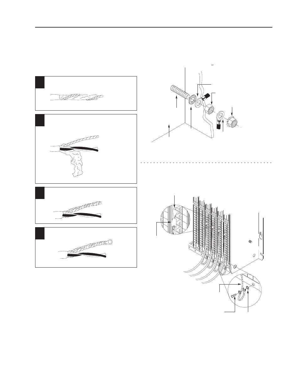
Groundthe Module
Use the following diagrams to ground your
I/O chassis and CFM module.
foil shield
20
1
2
3
4
Remove a length ofcable
jacket from the Belden 8761 cable.
Pull the foil shield and bare
drain wire from the insulated wires.
bare drain wire
insulated wires
Twist the foil shield and drain
wire together to form a single strand.
Attach a ground lug.
20104
externalĆtooth
washers
#10 threadĆforming screw
19923
shield and drain
twisted together
SingleĆpoint Grounding
Extend shield to termination point.
Expose just enough cable to adequately
terminate inner conductors.
Use heat shrink tubing
or other suitable
insulation where wire
exits cable jacket.
19480
grounding stud
À
Use the cup washer ifcrimpĆon lugs are not used.
Chassis Ground
When you connect grounding conductors to the I/O chassis
grounding stud, place a star washer under the first lug, then
place a nut with captive lock washer on top ofeach ground lug.
Torque the nut with captive washer to 18(+3) pound-inches.
ground lug
ground lug
À
star
washer
I/O chassis
side plate
nut and captive
washer
shield and drain
twisted together
nut