Rockwell Automation 1494F-M2_S2 Disconnect Handle for Disconnect Switches and Circuit Breakers User Manual
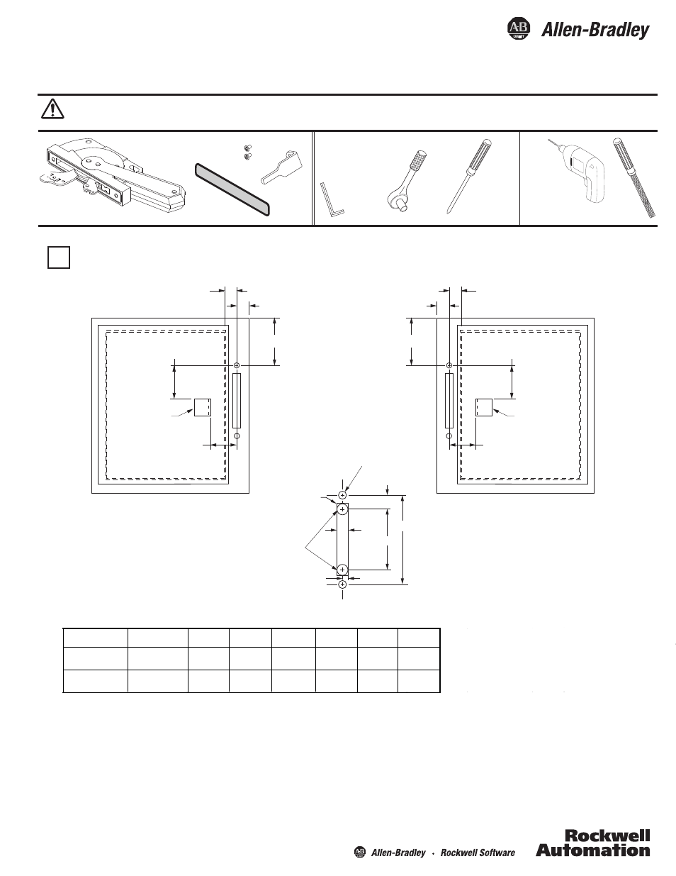
Locating and drilling handle holes tools needed
Installation Instructions
Bulletin 1494F Disconnect Handle for Disconnect Switches and Circuit Breakers
(Cat 1494F-M2; 1494F-S2)
WARNING: To prevent electrical shock, disconnect from power source before installing or servicing. Follow NFPA 70E requirements. Install in suitable enclosure. Keep free from contaminants.
Installation, adjustments, putting into service, use, assembly, disassembly, and maintenance shall be carried out by suitably trained personnel in accordance with applicable code of practice. In case of malfunction or
damage, no attempts at repair should be made. The product should be returned to the manufacturer for repair. Do not dismantle the product.
A
B
B
A
Door Catch
Mounting
Bracket
Right Hand Flange
Left Hand Flange
Door Catch
Mounting
Bracket
1
-5/8”
1
-5/8”
1
-7/32”
MAX.
1
-7/32”
MAX.
3
-49/64”
3
-49/64”
1
Square corners
or up to
1/4" radius
(2) .328” Dia.
Holes
Locating and Drilling Handle Holes
Tools
Needed:
5”
1/2"
9/16"
1/4"
Switch Rating
Circuit Breaker
Frame Size
A
(MIN)
B
(MIN)
(MIN)
C
(MAX)
D
E
F
400 A
14-3/16”
1-1/8”
1-7/32”
1-5/8”
5/8”
5/8”
600 A
18-3/16”
1-1/8”
1-7/32”
1-5/8”
3/4”
3/4”
800 A
1200 A
To make slot,
drill (2) 1/2"
diameter holes
and remove burrs
Notes:
·
E
nclosures with a Flange Thickness less than 3/16" use dimensions shown on this instruction sheet.
·
E
nclosures with a Flange Thickness 3/16" and greater use dimensions in Mounting Kit 1494V-H6.
This kit requires “B” dimension of 1-7/32” minimum.
6
-1/2”
7/16”
21/64” (.328”)
and
1/2” (.500”)
Slotted
1/4” Wide Slot
File
Allen Wrench
1/8” (.125”)
* - Only needed for handle cutout
*
*
*