V. wiring diagrams (cont’d), Cable “b” cable “a – Rockwell Automation 1492-CM1771-LA004 Analog & Digital I/O Conversion Module User Manual
Page 10
(10)
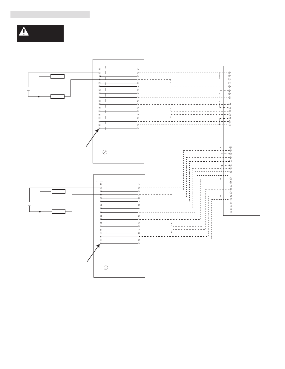
V. Wiring Diagrams (Cont’d)
There are several key application considerations and system specifications (bottom of drawing) when
using these components (conversion module, cable and input module). Read and understand these
considerations before installation.
WARNING
Conversion Module
1492-CM1771-LA004
Conversion Module
1492-CM1771-LA004
1771-WF Swing Arm
From 1771-OQ
1771-WF Swing Arm
From 1771-OQ
Cable
1492-C005005XT
1756-OB16I
Conversion: 1771-OQ (2) to 1756-OB16I (1)
PN-114290
DIR 10000060101 (Version 01)
Publication 1492-IN048B-EN-E
18
17
16
15
14
13
12
11
10
9
8
7
4
3
2
6
1
5
Orange/Red
White/Red
Green/White
Blue/White
Orange/Black
Red/White
Black/Red
Blue/Black
Black/White
Green/Black
Blue
Orange
Red/Black
White/Black
18
14
13
12
11
8
6
5
17
16
15
4
3
2
1
10
9
7
Black
White
Red
Green
2
1
4
3
10
14
13
DC-1
OUTPUT-0
OUTPUT 1
DC-2
OUTPUT 2
DC-2
6
8
12
5
9
7
11
15
OUTPUT 3
DC-3
DC-3
DC-4
16
DC-4
DC-1
OUTPUT-4
OUTPUT 5
OUTPUT 6
OUTPUT 7
LOAD
+
-
LOAD
18
17
16
15
14
13
12
11
10
9
8
7
4
3
2
6
1
5
Orange/Red
White/Red
Green/White
Blue/White
Orange/Black
Red/White
Black/Red
Blue/Black
Black/White
Green/Black
Blue
Orange
Red/Black
White/Black
18
14
13
12
11
8
6
5
17
16
15
4
3
2
1
10
9
7
Black
White
Red
Green
18
17
20
19
26
30
29
DC-1
OUTPUT-8
OUTPUT 9
DC-2
OUTPUT 10
DC-2
22
24
28
21
25
23
27
31
OUTPUT 11
DC-3
DC-3
DC-4
32
DC-4
DC-1
OUTPUT-12
OUTPUT 13
OUTPUT 14
OUTPUT 15
LOAD
+
-
LOAD
NOT USED
33
34
35
36
NOT USED
NOT USED
NOT USED
Cable “B”
Cable “A”
DC-1
OUTPUT-0
OUTPUT 1
DC-2
OUTPUT 2
DC-2
OUTPUT 3
DC-3
DC-3
DC-4
DC-4
DC-1
OUTPUT-4
OUTPUT 5
OUTPUT 6
OUTPUT 7
Not Used
Not Used
DC-1
OUTPUT-8
OUTPUT 9
DC-2
OUTPUT 10
DC-2
OUTPUT 11
DC-3
DC-3
DC-4
DC-4
DC-1
OUTPUT-12
OUTPUT 13
OUTPUT 14
OUTPUT 15
Not Used
Not Used
Conversion Module Installation and Application Considerations
This Bul. 1492 cable consists of 2 separate cables (cable “A” and cable “B”) wired to one 1756-OB16I RTB. Each cable can be either
0.5M or 1.0M (005=0.5M, 010=1.0M). Ensure that cable A and cable B are connected to the correct module in the conversion
The 1771-OQ module output resistive current limits versus 1756-OB16I limits are as follows:
1771-OQ
1756-OB16I w/ 1492-C005005XT
a) Current/Point
2.25A
2A
b) Current/Module
9A
8A
c) Surge Current/Point 4A for 10ms
4A for 10ms
The 1771-OQ is rated 10V to 32V DC. The 1756-OB16I is rated 10V to 30V DC.
Refer to your 1771-OQ and 1756-OB16I Installation Manual wiring schematics and diagrams for more details. Ensure 1756 output
module ratings are not exceeded.
[Reference Doc: 41171-033 (Version 00)]