Window mode – Rockwell Automation 873P Ultrasonic Single Analog Output Sensors Installation Instructions User Manual
Page 2
Rockwell Automation 873P-IN005A-EN-P—October 2014
2 873P Ultrasonic Single Analog Output Sensors
Window Mode
In this sensing mode, you teach the sensor a near set point and far
set point within the defined sensing range of the sensor. P1 and
P2 define the analog output slope. P1 determines the 4 mA/0V DC
position and P2 determines the 20 mA/10V DC position. The
analog output is scaled between the two taught set points.
Rising ramp: current or voltage values increase as the target
distance increases from the sensor.
Falling ramp: current or voltage values decrease as the target
distance increases from the sensor.
Set Point 1 (P1)
1. Place target at the desired near/far set point.
a. The near set point first yields a rising ramp.
b. The far set point first yields a falling ramp.
2. With the target still in place, press the teach button, then
release.
The yellow and green LEDs flash simultaneously, indicating that
the first set point P1 is now set. The sensor is waiting for the last
set point.
Set Point 2 (P2)
1. Place the target at the desired far/near set point.
2. Press the teach button and release. The sensor is ready to
operate.
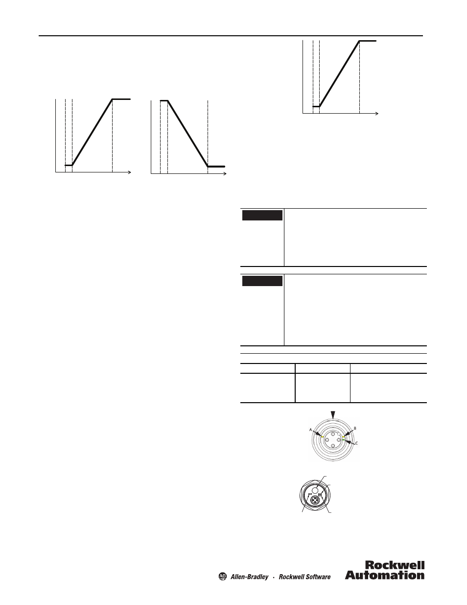
One Set Point Mode
In this sensing mode, a set point is taught in the defined sensing
range. The working range of the sensor becomes the minimum
sensing distance to a user-taught set point. Depending on where
the set point is taught, the output will turn ON when the target
passes between the minimum sensing distance of the sensor and
the taught set point. The analog output is scaled between those
two set points. When using the One Set Point mode, it is only
possible to configure the sensor for rising ramp analog
output. It is not possible to configure the sensor for a falling
ramp.
20 mA/
10V DC
Rising
Ramp
Pin 4
(BK)
Blind Z
one
4 mA/
0V DC
mm
P2
P1
BZ
20 mA/
10V DC
Falling
Ramp
Pin 4
(BK)
Blind Z
one
4 mA/
0V DC
mm
P1
P2
BZ
1. Place the target at the desired set point.
2. Press and release the teach button. The yellow and green LEDs
flash simultaneously, indicating that the sensor has learned the
set point.
3. Keeping the target in the same position, press and release the
teach button. The yellow LED blinks twice to indicate that the
sensor is ready for use. The minimum sensing distance is
indicated in the Specifications table.
When configuring the sensor for One Set Point
mode, it is very important that the target is at the
exact same distance for both the first and second
push of the teach button. If the target (or sensor)
has moved even slightly, the detected ranges will
be different for the two pushes of the teach
button, and the sensor will be configured for
Window Mode.
The green and yellow LEDs flash asynchronously
for about two seconds indicating there is no
target present within the sensing range of the
sensor and therefore no set point to teach. When
this happens, the 873P ignores this teach
attempt and restores its previous settings. By
comparison, when an object is detected during
the teach, the yellow and green LEDs flash
synchronously and continue flashing until the
second push of the teach button.
Single Analog Output Indicator LED Functions
LED
Color
Function
A
Yellow
Output state
B
Yellow
Teach function
C
Green
ECHO LED/ Teach function
20 mA/
10V DC
Rising
Ramp
Pin 4
(BK)
Blind Z
one
4 mA
0V DC
mm
P1=P2
Minimum
Sensing
Distance
BZ
IMPORTANT
IMPORTANT
1
2
3
4
(Yellow)
Teach
(Green)
Echo/teach
(Yellow)
Output state
Teach button
M18 LEDs
Teach button
Yellow LED B
Teach function
Yellow LED A
output state
Green LED C
A
B
C
M30 LEDs
Echo LED/teach function