Door and hardware construction, Guidelines, Instructions – Rockwell Automation 1494D Flange Mounted Circuit Breaker Operators - 100, 225, and 400 Ampere Frame Sizes User Manual
Page 4: For additional door catch instructions, Large enclosures, Instructions 1
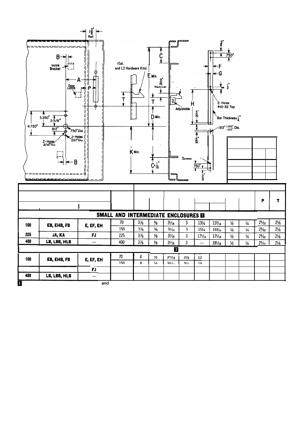
DOOR AND HARDWARE CONSTRUCTION
Small and intermediate
Enclosures
Nos.1494F-L1
Large Enclosures
(Cat. No. 1494F-L4
Hardware Kit)
I
M Min.
Clearance
Holes
for 2 - #1/4-20
Hardware
Dimensions
Kits
in Inches
Catalog No.
K
M
Min.
1494F-L1
3
1
/4
-
1494F-L2
-
5
1494F-L4 -
6
I
- - - - - - - - - - - - -
Amperes
Circuit Breaker
Dimensions in Inches
Frame Size Maximum
Current
E
I
Rating
(Amperes)
A B C D F G
W ‘estlnghouse
ITE
ITE WEST.
P T
25/32
2%
225
LARGE ENCLOSURES
I
1
3
11
3
1
13
1
/8
13
1
/
8
5
/8
5
/16
2
1
/4
1
9
/16
150 4
2
3
/16
3 /
8
14
7
/8
14
13
/16
5
/8
5
/16
2
1
/4
1
9
/16
225 4
1
/2
3
11
/16
3
1
/8
16
3
/16
16
3
/16
5
/8
5
/16
2
1
/4
1
9
/16
400 4
1
/2
3
11
/16
3
1
/8
-
1 7
3
/ 1 6
5
/8
5
/16
2
1
/4
1
9
/16
p
latching); 1494F-L2 (top and bottom latching); and 1494F-L3 (side latching accessory
225
JA, KA
Use with Hardware Kits 1494F-L1 (to
for 1494F-L2);
side
q
Use with Hardware Kit 1494F-L4 (top, side and bottom latching).
GUIDELINES
Small Enclosures: 30” high or less with 2 or 3 point latch-
ing. Intermediate Enclosures: 30” thru 48” high with 3
point latching. Large Enclosures: Above 48” high with 3
point latching.
to the enclosure door. However, if a specific installa-
tion permits, holes can be drilled in the door catch and
guide bracket(s) using the projections as centers. Then,
after proper location and using them as templates,
corresponding holes can be drilled in the enclosure
door. Door catch and guide bracket(s) are then fas-
tened to the enclosure door with hardware furnished
by user.
6.
Establish the length of the top locking bar by meas-
uring Dimensions “E” and subtracting 3/4" for Kits L1
and L2; subtract 1-1/8" for Kit L4. Determine the
length of the bottom locking bar by measuring Dimen-
sion “K” and subtracting 3/4" for Kit L2; subtract
l-l/8" for Kit L4. Dimension “H” is determined by
measuring Dimension “D” and adding 3-3/4" for Kits
L1 and L2; add 3-5/8" for Kit L4. Locate, drill, and
tap holes where necessary. NOTE:
These standard mill
rectangular locking bars are not supplied with these
kits.
7. The door locking hardware assembly can now be at-
tached to the door.
INSTRUCTIONS
1.
Check all minimum enclosure and door dimensions
required for installation. Refer to Page
2. Select the dimensions from above which apply to the
roller latching arrangement to be installed.
NOTE: Door catch supplied with operating mechanism
is not to be used with these door hardware kits.
3. Locate holes in door to secure handle assembly.
4. Determine Dimensions “B” and “C” to locate locking
bar guide bracket(s).
5. Locate door catch using “P” and “T” dimensions. Lo-
cation varies with each hardware kit. On 1494F-L4
hardware kits, attach the adjustable catch after the
support bracket is located. NOTE: Door catch and
guide bracket(s) are made with projections for welding