Rockwell Automation 1494D Flange Mounted Circuit Breaker Operators - 100, 225, and 400 Ampere Frame Sizes User Manual
Flange mounted circuit breaker operators, 1494d, Instructions
I
BULLETIN
INSTRUCTIONS
1494D
FLANGE MOUNTED CIRCUIT BREAKER OPERATORS
FOR 100, 225 AND 400 AMPERE FRAMES
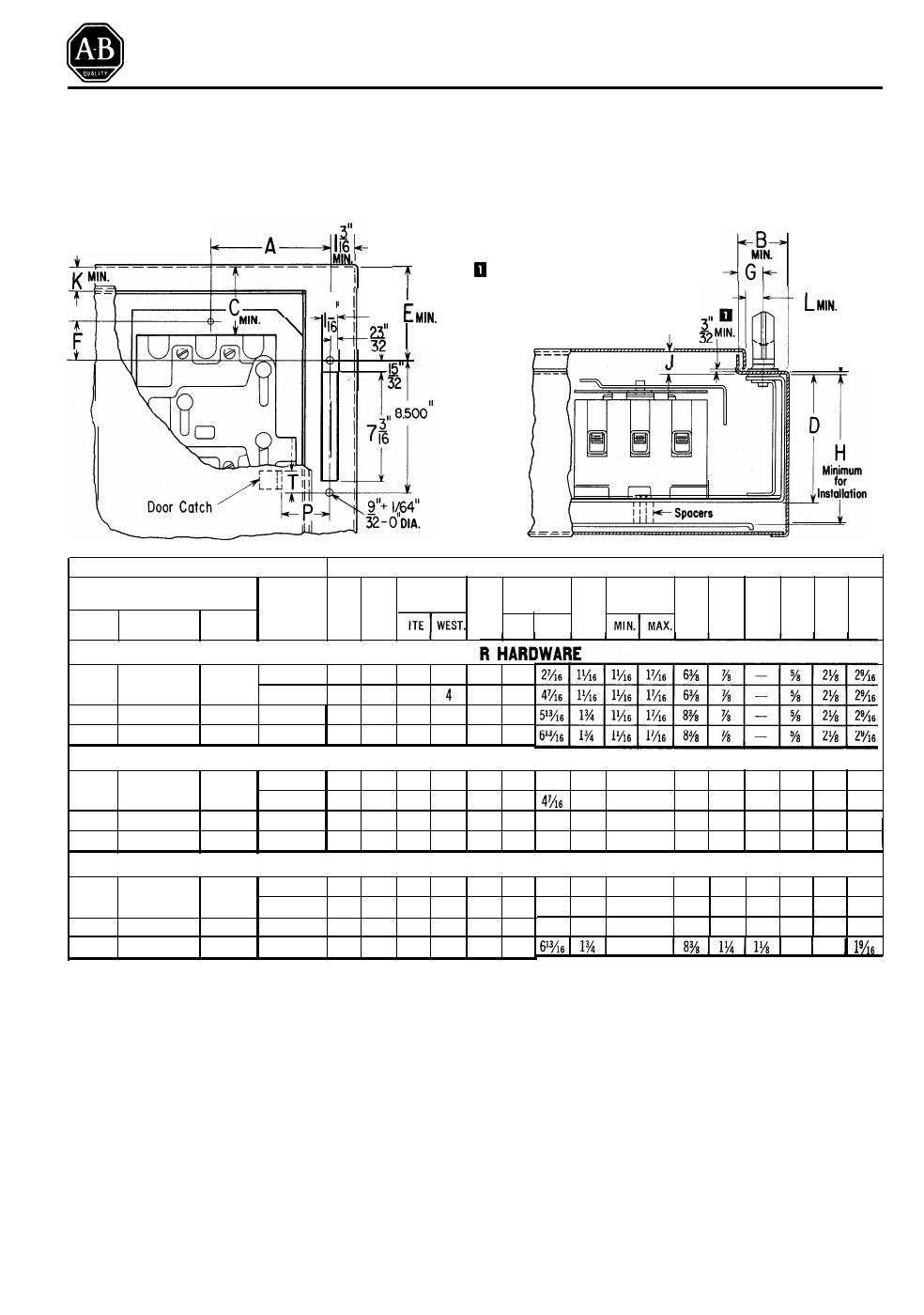
ENCLOSURE CONSTRUCTION
3/32" minimum is required
the door to clear the flange
for
I
7
I
plate. A smaller dimension in-
creases “G” and “B” by 3/1 6”
minimum and “L” by 3/8" min.
-
Enclosure Flange
#10 Gauge Max.
C i r c u i t B r e a k e r
Dimensions in Inches
Frame Size
Maximum
Current A
B
C
E G
D F H J K L P
T
AmperesWestinghouse ITE
Rating
(Amperes)
ITE WEST.
WITHOUT DOO
100 EB, EHB, FB E, EF , E H 70 4
5
/16
2
1
/4
2 2 4
15
/16
2
1
/2
150 4
5
/16
2
1
/
4
4
/
4
15
/16
4
1
/2
225
J A , K A FJ 225 3
1
/8
2
1
/4
5
5 6
15
/16
5
13
/16
400 LB,LBB, HLB - 400 3
7
/8
2
1
/4
-
6
6
15
/16
-
SMALL & INTERMEDIATE ENCLOSURES WITH DOOR HARDWARE
100
EB,EHB,FB E,EF,EH
70
4
5
/16
2
9
/16
2 2 4
15
/16
2
1
/2
2
1
/16
1
1
/16
1
3
/8
6
3
/8
7
/8
11
/16
5
/8
2
5
/32
2
1
/8
150 4
5
/16
2
9
/16
4 4 4
15
/16
4
1
/2
1
1
/16
1
3
/8
6
3
/8
7
/8
11
/16
5
/8
2
5
/32
2
1
/8
225
J A , K A FJ 225 3
7
/8
2
9
/16
5 5 6
15
/16
5
13
/16
5
13
/16
1
3
/4
1
3
/8
6
7
/8
7
/8
11
/16
5
/8
2
5
/32
2
1
/8
400
LB,LBB,HLB
- 400 3
7
/8
2
9
/16
-
6 6
15
/16
- 6
13
/16
1
3
/4
1
3
/8
6
7
/8
7
/8
11
/16
5
/8
2
1
/8
2
9
/16
LARGE ENCLOSURES WITH DOOR HARDWARE
100 EB, EHB, FB E,EF, EH
70 4
5
/16
2
9
/16
2
1
/4
2
5
/16
4
15
/16
2
3
/4
150 4
5
/16
2
9
/16
4
4 4
15
/16
4
1
/2
225 JA, KA FJ
225
3
7
/8
2
9
/16
5
5 6
13
/16
5
13/16
400
LB,LBB,HLB
- 400
3
7
/8
2
9
/16
-
6 6
15
/16
-
INSTRUCTIONS
2
3
/4
1
1
/16
1
3
/8
6
3
/8
1
1
/4
1
1
/8
5
/8
2
1
/4
1
9
/16
4
7
/16
1
1
/16
1
3
/8
6
3
/8
1
1
/4
1
1
/8
5
/8
2
1
/4
1
9
/16
5
13
/16
1
3
/4
1
3
/8
8
3
/8
1
1
/4
1
1
/8
5
/8
2
1
/4
1
9
/16
1
3
/8
5
/8
2
1
/4
NOTE: The circuit breakers are not supplied with these
kits and are shown only for convenience.
1.
Select the table which applies to your enclosure.
2 .
D e t e r m i n e t h e e n c l o s u r e f l a n g e w i d t h “ B ” a n d t h e
mounting depth “H” to ensure the cabinet is at least as
large as these minimum values.
3.
Refer to N.E.C. for required wire bending space, Di-
mension “C”. The minimum value given for “C” is the
minimum wire bending space for the maximum wire
size that can be connected to each circuit breaker for
its current rating.
4.
Provide slot and mounting holes on the right hand
flange as indicated.
5.
Provide spacer brackets for the circuit breaker mount-
ing plate as shown. Typical spacer brackets are shown
Please note notch and clearance holes re-
quired for slide assembly.
6.
Locate door catch using "P" and “T”. NOTE: With
enclosures using door hardware disregard the door
catch supplied with operating mechanism. Instead, use
door catch furnished with door hardware, and refer to
for additional door catch instructions.
Publication 1494D-5.0-December 1975
1494D-800
Supersedes Instructions
Dated June, 1970
Document Outline
- Flange Mounted Circuit Breaker Operators - For 100, 225, and 400 Ampere Frames
- Enclosure Construction
- Instructions
- Operator and Slide Mechanism
- Circuit Breaker Mounting
- Dimensions
- Installation Instructions
- Door and Hardware Construction
- Guidelines
- Instructions
- Installation of Door Hardware Kits
- Instructions
- Pub. No.