Rockwell Automation 1102C-PKxx 400A / 600A Vacuum Contactor DC Coil Replacement User Manual
Page 3
42052-092
G. Ushakow
N/A
N/A
N/A
42052
1006490
1
INSTRUCTION SHEET
BULLETIN 1102C 400A/600A VACUUM CONTACTOR
DC COIL REPLACEMENT
2-20-04
Mark Jutz
2-20-04
D. Josef
2-20-04
3
4
REVISION
AUTHORIZATION
DIMENSIONS APPLY BEFORE
SURFACE TREATMENT
H
A
B
C
D
E
F
G
(DIMENSIONS IN INCHES)
TOLERANCES UNLESS
OTHERWISE SPECIFIED
REFERENCE
SHEET
OF
DWG.
B
DR.
CHKD.
APPD.
DATE
DATE
DATE
±
±
±
ANGLES:
.XXX:
.XX:
THIS DRAWING IS THE PROPERTY OF
THE ALLEN-BRADLEY CO. INC.
AND MAY NOT BE COPIED, USED OR
DISCLOSED FOR ANY PURPOSE EXCEPT
AS AUTHORIZED IN WRITING BY
THE ALLEN-BRADLEY CO. INC.
LOCATION : MILWAUKEE,
WISCONSIN
U.S.A.
SIZE
1
2
3
4
5
6
7
8
E - DOC
Coil Replacement (Cont'd)
11. Replace the Return Springs by placing them over the spring support pins located within the coil magnet core
assembly making sure the return springs are properly seated and not interfering with any of the control wiring
(Figure 3).
12. Carefully replace the Main Housing assembly loosely, making sure it is orientated correctly. Ensure that no wires
are pinched between housing and baseplate. Carefully locate the magnetic armature poles (the poles sticking down
from the upper housing assembly) into the coil magnet core assembly. Note: This is a blind operation with careful side to
side motion. Pay close attention to alignment of the locating bosses located at the bottom of the main housing assembly.
Locate the Main Housing assembly with the main housing locating bosses to the mounting plate while compressing the
return springs with the main housing. Start the four Main Housing screws into the mounting plate. Tighten the mounting
screws equally in a diagonal pattern approximately two turns at a time until torqued to 28 lb-inches in the same diagonal
pattern.
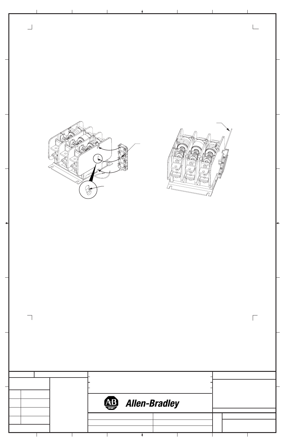
13. Re-install the Auxiliary (Figures 7A & 7B). First, rotate the Retainer upwards. Next, insert the lower tab into the
recess on the side of the contactor base. With proper installation, the Actuator will fit into the hole in the slot in the side of
the contactor housing. Using a thin rod or flat blade, lift the Actuator up as necessary to insert it into the slot mentioned.
Rotate the Retainer to its original position, which will slide over the upper tab on the
Auxiliary.
11. Reinstall the cover and secure it with the original mounting hardware. Torque the four screws in a diagonal
pattern to 12 lb-inches.
(See Figure 1).
12. Reattach the coil wire leads and any auxiliary control wires to the Auxiliary (torque to 7 lb-inches).
13. Reinstall the contactor. Torque mounting screws to 50 - 75 lb-inches.
14. Reconnect the line and load conductors and tighten the main terminal hardware and bolts to 180 - 210 lb-
inches.
Actuator
must fit into slot
shown
Figure 7A
Figure 7B
Auxiliary
Actuator
Thin rod or flat blade
(3)