Rockwell Automation 1102C-PKxx 400A / 600A Vacuum Contactor DC Coil Replacement User Manual
Page 2
42052-092
G. Ushakow
N/A
N/A
N/A
42052
1006490
1
INSTRUCTION SHEET
BULLETIN 1102C 400A/600A VACUUM CONTACTOR
DC COIL REPLACEMENT
2-20-04
Mark Jutz
2-20-04
D. Josef
2-20-04
2
4
REVISION
AUTHORIZATION
DIMENSIONS APPLY BEFORE
SURFACE TREATMENT
H
A
B
C
D
E
F
G
(DIMENSIONS IN INCHES)
TOLERANCES UNLESS
OTHERWISE SPECIFIED
REFERENCE
SHEET
OF
DWG.
B
DR.
CHKD.
APPD.
DATE
DATE
DATE
±
±
±
ANGLES:
.XXX:
.XX:
THIS DRAWING IS THE PROPERTY OF
THE ALLEN-BRADLEY CO. INC.
AND MAY NOT BE COPIED, USED OR
DISCLOSED FOR ANY PURPOSE EXCEPT
AS AUTHORIZED IN WRITING BY
THE ALLEN-BRADLEY CO. INC.
LOCATION : MILWAUKEE,
WISCONSIN
U.S.A.
SIZE
1
2
3
4
5
6
7
8
E - DOC
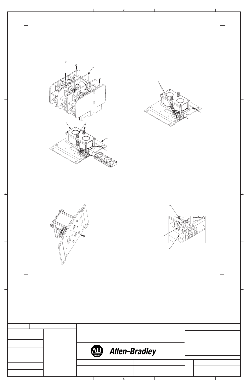
Coil Replacement (Cont'd)
6. While supporting the Main Housing, remove the Main Housing from the Baseplate by removing the (4) screws which
hold the housing to the Baseplate. A long philips-head screwdriver (6" or longer) is needed as the four screws are in
deep wells (holes) in the Main Housing. Remove the shorter screws first. Separate the main housing assembly from
the Baseplate and set it aside
(Figure 3).
7. Remove the wires to the rectifier (terminals "+" & "-") (Figure 4).
8. Remove the Return Springs and set them aside (Figure 3). Turn the Base Assembly over and remove the (4)
screws that secure the Coil Assembly to the Baseplate.
(Figure 5).
9. Install new Coil Assembly in position using (4) screws (torque to 30 - 45 lb-inches).
10. Connect the two wires (with the slip-on connectors) to the rectifier. Connect the red wire to the "+" terminal and
the yellow & white wires to the "-" terminal
(Figure 6).
Figure 3
Figure 6
Figure 5
Figure 4
Baseplate
Main
Housing
Return
Springs
Coil
Assembly
Red wire to "+" terminal
Yellow and white wires to "-" terminal
Rectifier
Remove these
wires from
rectifier
(2)