Installation, Inspection, Location – Rockwell Automation 1329R Std. Industrial AC Induction Motors User Manual
Page 6: Inspection location
6
Standard Industrial AC Induction Motors
Installation
Inspection
After the motor is unpacked, examine the nameplate data to see that it
agrees with the power circuit to which it is to be connected. The
motor will operate with frequency not more than 5% and voltage not
more than 10% above or below the nameplate data, or combined
variation of voltage and frequency of not more than 10% above or be
low nameplate data. Efficiency, power factor and current may vary
from nameplate data. Performance within these voltage and
frequency variations will not necessarily be in accordance with the
standards established for operation at rated voltage and frequency.
Location
The motor should be installed in a location compatible with the motor
enclosure and specific ambient.
To allow adequate air flow, the following clearances must be
maintained between the motor and any obstruction:
TEFC (IC0141) Enclosures
Fan Cover Air Intake
180-210T Frame
25.4 mm (1.00 in.)
250-449T Frame
101.6 mm (4.00 in.)
IEC 112 - 132
25.0 mm (0.98 in.)
IEC 160 - 280
100.0 mm (3.94)
Exhaust
Envelope equal to the “P” dimension on the motor dimension sheet
Protected Enclosures
Bracket Intake
Same as TEFC
Frame Exhaust
Exhaust out the sides-envelope a minimum of the “P” dimension plus
50.0 mm (1.97 in.). Exhaust out the end-same as intake.
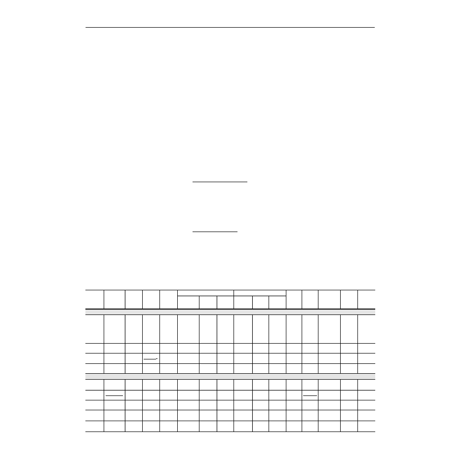
Table B
General Effect of Voltage & Frequency Variation on Induction-motor Characteristics
NOTE: This table shows goneral effects, which will vary somewhat for specific ratings.
Variation
Starting &
Maximum
Running
Torque
Sync
Speed
Slip %
Full Load
Speed
Efficiency
Power Factor/COS
Full
Load
Current
Starting
Current
Temperature
Rise
(full load)
Maximum
Overload
Capacity
Magnetic
Noise
(no-load in
particular)
Full-Load
3/4 Load
1/2 Load
Full Load
3/4 Load
1/2 Load
Voltage Variation:
120%
voltage
Increase
44%
No
change
Decrease
30%
Increase
1.5%
6-0%
Decrease
(1-75 HP)
0-3%
Increase
(100-200 HP)
Decrease
1/2-2
points
Decrease
7-20
points
Decrease
5-15 points
Decrease
10-30
points
Decrease
15-40
points
Increase
12%
Increase
20%
Increase 5-6
degrees C.
(1-75 HP)
Decrease 3-4
degrees C.
(100-200 HP)
Increase
44%
Noticeable
increase
110%
voltage
Increase
21%
No
change
Decrease
17%
Increase
1%
Slight
decrease
Practically
no change
Decrease
1-2 points
Decrease
5-10 points
Decrease
5 points
Decrease
5-6 points
Increase
2-4%
Increase
10-12%
Increase 3-4
degrees C.
Increase
21%
Increase
slightly
Functions
of Voltage
(voltage)
2
Constant
1
(voltage)
2
(sync
speed slip)
voltage
(voltage)
2
90%
Voltage
Decrease
19%
No
change
Increase
23%
Decrease
1-1/2%
Decrease
2 points
Practically
no change
Increase
1-2 points
Increase
5 points
Increase
2-3 points
Increase
4-5 points
Increase
11%
Decrease
10-12%
Increase 6-7
degrees C.
Decrease
19%
Slight
decrease
Frequency Variation:
105%
frequency
Decrease
10%
Increase
5%
Practically
no change
Increase
5%
Slight
increase
Slight
increase
Slight
increase
Slight
increase
Slight
increase
Slight
increase
Slight
decrease
Decrease
5-6%
Slight
decrease
Slight
decrease
Slight
decrease
Function of
frequency
1
(frequency)
2
Frequency
(sync
speed slip)
1
frequency
95%
frequency
Increase
11%
Decrease
5%
Practically
no change
Decrease
5%
Slight
decrease
Slight
decrease
Slight
decrease
Slight
decrease
Slight
decrease
Slight
decrease
Slight
increase
Increase
5-6%
Increase
slightly
Increase
slightly
Increase
slightly
1% phase
unbalance
Slight
decrease
Slight
decrease
Slight
decrease
2%
decrease
5-6%
decrease
1-1/2%
increase
Slight
decrease
2%
increase
2% phase
unbalance
Slight
decrease
Slight
decrease
Slight
decrease
8%
decrease
7%
decrease
3%
increase
Slight
decrease
8%
increase