Quick installation guide (continued), Attention, Connecting rod installation – Rockwell Automation 1494V-DS30 - DSX200 Disconnect Switch and Accessories User Manual
Page 3
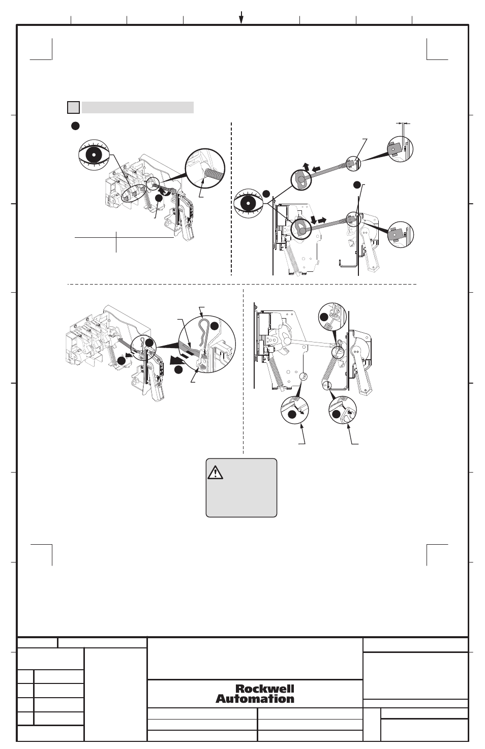
Connecting Rod Installation
4
Verify that disconnect switch and handle are in "OFF"
position. (Switch blades will be visible)
Drive Bar
Pull up
(30A - 60A - 100A)
1
2
Rotate connecting rod into
drive bar (see table).
3
4
Enclosure depth
8 in. or less
Enclosure depth
greater than 8 in.
CHECK FOR PROPER
OPERATION
ATTENTION
7
8b
8a
Push rod down and
verify if rod is nearly
touching bottom of bolt
head. (If not, rotate rod
up to 5 full turns in
either direction)
(200A)
Push down
Push rod down and verify if rod
is approximately 1/8" from
touching bottom of bolt head.
(If not, rotate rod up to 5 full
turns in either direction)
1/8" Gap
Switch Rating
30A - 60A - 100A
200A
Full Turns Engagement
10
13
BULLETIN 1494V VARIABLE DEPTH DISCONNECT SWITCH
INSTALLATION INSTRUCTION SHEET
5
1020139
42052-116
OF
N/A
N/A
N/A
REVISION
AUTHORIZATION
DR.
CHKD.
APPD.
DATE
DATE
DATE
E - DOC
LOCATION: MILWAUKEE, WISCONSIN U.S.A.
DWG.
SIZE
SHEET
B
1
2
3
4
5
6
7
8
A
B
C
D
E
F
G
H
REFERENCE
DIMENSIONS APPLY BEFORE
SURFACE TREATMENT
(DIMENSIONS IN INCHES)
TOLERANCES UNLESS
OTHERWISE SPECIFIED
.XX:
.XXX:
ANGLES:
42052
- - - - - - -
- - - - - - -
- - - - - - -
- - - - - - -
- - - - - - -
- - - - - - -
THIS DRAWING IS THE PROPERTY OF
ROCKWELL AUTOMATION, INC.
OR ITS SUBSIDIARIES AND MAY NOT BE COPIED,
USED OR DISCLOSED FOR ANY PURPOSE
EXCEPT AS AUTHORIZED IN WRITING BY
ROCKWELL AUTOMATION, INC.
3
17
6
1021282
7
1032142
QUICK INSTALLATION GUIDE (CONTINUED)
(3)
Connecting
Rod
Hitch Pin
Primary Link
5
6
5
6