Vi. wiring diagrams (cont’d), Cable”a” cable”b – Rockwell Automation 1492-CM1771-LD0012 Field Wire Conversion Module User Manual
Page 6
PN-114284
DIR 10000060095 (Version 01)
Publication 1492-IN042B-EN-E
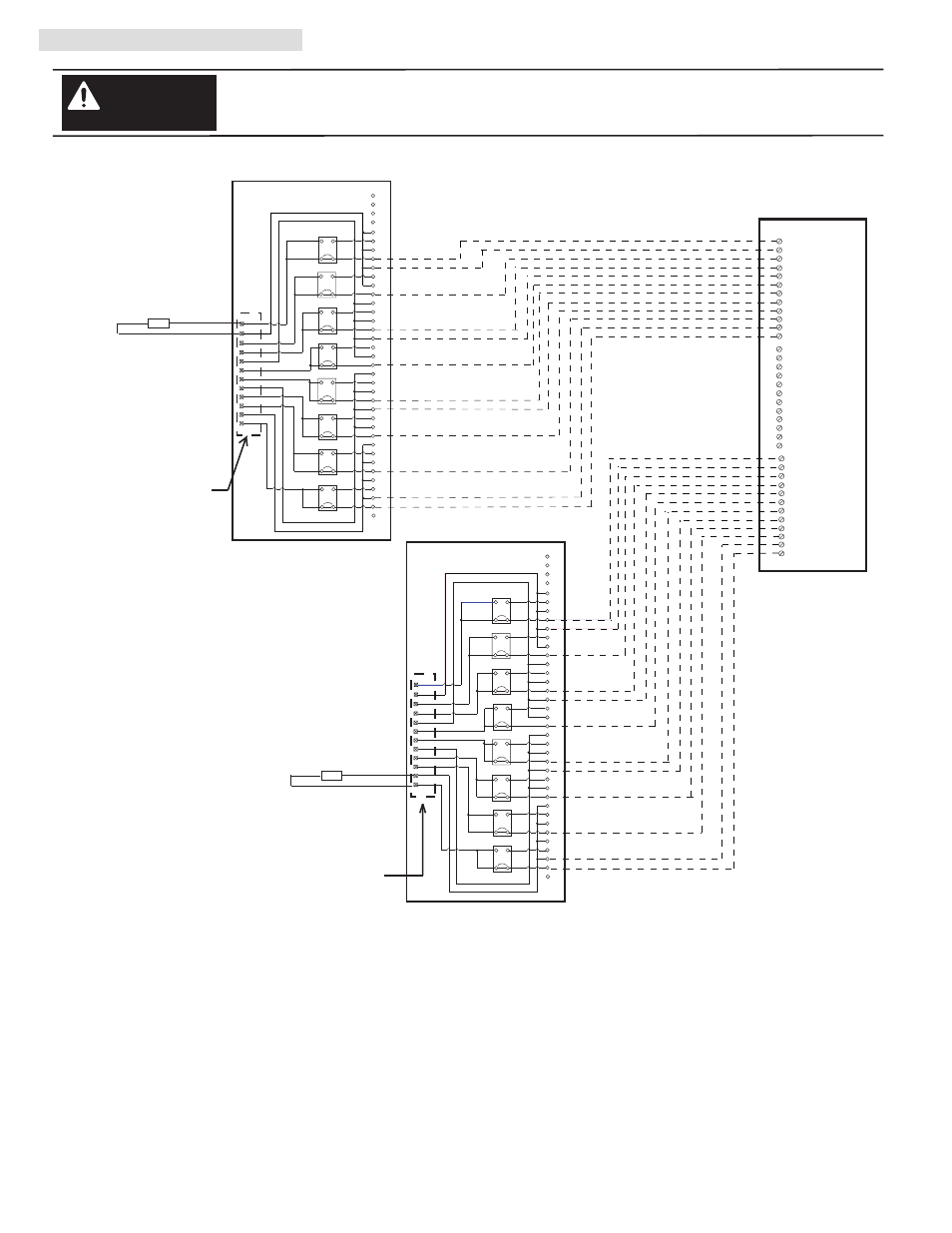
VI. Wiring Diagrams (Cont’d)
There are several key application considerations and system specifications (bottom of drawing) when
using these components (conversion module, cable and input module). Read and understand these
considerations before installation.
WARNING
Conversion Module
1492-CM1771-LD012
Conversion Module
1492-CM1771-LD012
1771-WD Swing Arm
From 1771-ID01
1771-WD Swing Arm
From 1771-ID01
Cable
1492-C005005XL
1756-IM16I
Conversion: 1771-ID01 (2) to 1756-IM16I (1)
(6)
1
2
3
4
5
6
7
8
9
10
11
12
13
15
16
17
18
19
20
14
21
22
23
24
25
26
27
28
29
30
31
32
33
35
36
37
34
LOAD
1
2
3
4
5
6
Orange
Blue
White/Black
Red/Black
Green/Black
Orange/Black
Blue/Black
Black/White
Red/White
Green/White
Blue/White
Black/Red
White/Red
Orange/Red
Blue/Red
Red/Green
7
8
9
10
11
Orange/Green
Black/White/Red
White/Black/Red
Red/Black/White
Green/Black/White
Orange/Black/White
Blue/Black/White
Black/Red/Green
White/Red/Green
Red/Black/Green
Green/Black/Orange
Orange/Black/Green
Blue/White/Orange
Black/White/Orange
White/Red/Orange
Orange/White/Blue
12
L1
L2
1
5
6
7
8
9
10
11
12
2
3
4
1
3
2
4
N.O.
N.C.
1
3
2
4
N.O.
N.C.
JMP0
JMP1
1
3
2
4
N.O.
N.C.
JMP2
1
3
2
4
N.O.
N.C.
1
3
2
4
N.O.
N.C.
JMP3
JMP4
1
3
2
4
N.O.
N.C.
JMP5
1
3
2
4
N.O.
N.C.
JMP6
1
3
2
4
N.O.
N.C.
JMP7
1
2
3
4
5
6
7
8
9
10
11
12
13
15
16
17
18
19
20
14
21
22
23
24
25
26
27
28
29
30
31
32
33
35
36
37
34
Orange
Blue
White/Black
Red/Black
Green/Black
Orange/Black
Blue/Black
Black/White
Red/White
Green/White
Blue/White
Black/Red
White/Red
Orange/Red
Blue/Red
Red/Green
Orange/Green
Black/White/Red
White/Black/Red
Red/Black/White
Green/Black/White
Orange/Black/White
Blue/Black/White
Black/Red/Green
White/Red/Green
Red/Black/Green
Green/Black/Orange
Orange/Black/Green
Blue/White/Orange
Black/White/Orange
White/Red/Orange
Orange/White/Blue
1
5
6
7
8
9
10
11
12
2
3
4
1
3
2
4
N.O.
N.C.
1
3
2
4
N.O.
N.C.
JMP0
JMP1
1
3
2
4
N.O.
N.C.
JMP2
1
3
2
4
N.O.
N.C.
1
3
2
4
N.O.
N.C.
JMP3
JMP4
1
3
2
4
N.O.
N.C.
JMP5
1
3
2
4
N.O.
N.C.
JMP6
1
3
2
4
N.O.
N.C.
JMP7
25
26
27
28
29
30
31
32
33
34
35
36
NOT USED
NOT USED
NOT USED
13
14
15
16
17
18
19
20
21
22
23
24
L1-6
L2-6
L1-7
L2-7
L1-8
L2-8
L2-9
L1-9
L2-10
L1-10
L1-11
L2-11
NOT USED
NOT USED
NOT USED
NOT USED
NOT USED
NOT USED
NOT USED
NOT USED
L1-0
L2-0
L1-1
L2-1
L1-2
L2-2
L2-3
L1-3
L2-4
L1-4
L1-5
L2-5
LOAD
L1
L2
L1-6
L2-6
L1-7
L2-7
L1-8
L2-8
L2-9
L1-9
L2-10
L1-10
L1-11
L2-11
L1-0
L2-0
L1-1
L2-1
L1-2
L2-2
L2-3
L1-3
L2-4
L1-4
L1-5
L2-5
CABLE”A”
CABLE”B”
NOT USED
Conversion Module Installation and Application Considerations
This Bul. 1492 cable consists of 2 separate cables (cable “A” and cable “B”) wired to one 1756-IM16I RTB. Each cable can be either
0.5M or 1.0M (005=0.5M, 010=1.0M). Ensure that cable A and cable B are connected to the correct module in the conversion
The input delay times for the 1771-IM module versus the 1756-IM16I module are as follows:
1771-ID01
1756-IM16I w/ 1492-C005005XL
a) Off-to-On Delay
20ms (+/-10ms)
10ms max (plus selectable filter)
b) On-to-Off Delay
20ms (+/-10ms)
8ms max (plus selectable filter)
The 1771-ID01module had a jumper selection of N.O. and N.C. outputs. The 1756-IM16I has both N.O. and N.C. outputs, but
selection is by wiring termination on the 1756 swing arm. The 1492-CM1771-LD012 conversion module replaces the functionality
of the 1771-ID01 jumpers with eight jumpers (JMP0 through JMP7). In the default position, the output will be N.O. If a N.C. output is
required, change the jumper from pins 1-2 to pins 3-4.
Refer to your 1771-ID01 and 1756-IM16I Installation Manual wiring schematics and diagrams for more details. Ensure
1756 output module ratings are not exceeded.
[Reference Doc: 41171-015 (Version 00)]