Contactor interlock rod adjustment – Rockwell Automation 1500 Isolation Switch Handle Interlock Mechanism Engagement Replacement User Manual
Page 15
Bulletin 1500/1900 Isolation Switch Handle – Interlock Mechanism Replacement
15
1500-IN052C-EN-P – January 2007
To avoid shock hazards, lock out incoming power (see pages 1
to 4) before working on the equipment. Verify with a hot stick or
appropriate voltage measuring device that all circuits are voltage
free. Failure to do so may result in severe burns, injury or death.
1) Complete the Power Lock-out Procedure (see pages 1 to 4).
2) Open the medium voltage door. Use the Door Interlock Circumvention procedure
(described in Appendix A) to move the isolation switch handle halfway between
the OFF and ON position (see Figure 5). Keep the handle in this position until
the adjustment procedure is completed.
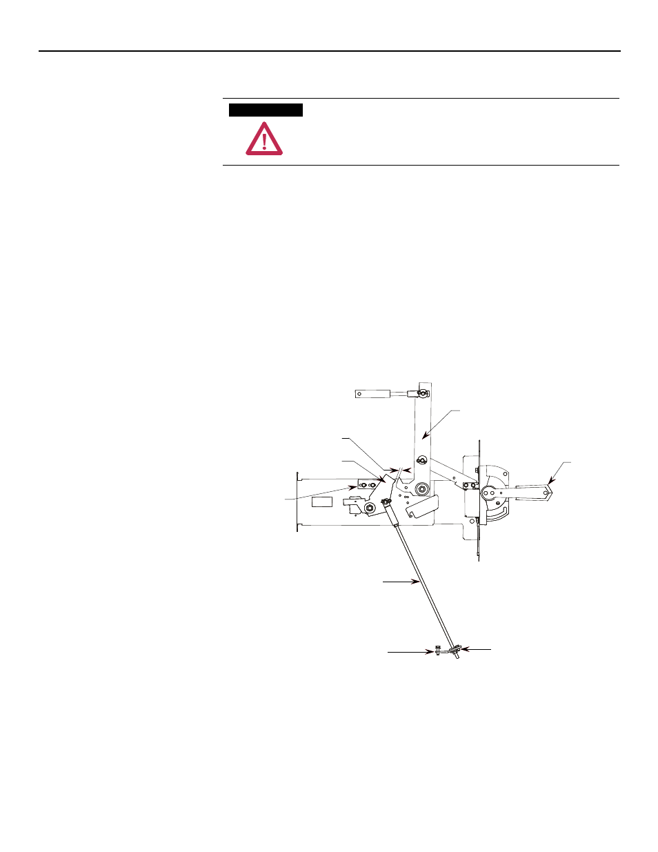
3) With the contactor in the OFF position, insert a 0.060 in. (1.5 mm) feeler gauge
in the gap between the interlock lever and the isolation switch operating lever.
The gap must be between 0.039 in. to 0.078 in. (1.0 mm to 2.0 mm).
4) To reduce the gap distance, follow steps 5-7.
To increase the gap distance follow steps 8-10.
Isolation Switch
Operating Lever
Stop Bracket
Switch Interlock Lever
Gap
0.09 in. to 0.078 in.
(1.0 mm to 2.0 mm)
Isolation
Switch Handle
at halfway
position
Contactor Interlock Rod
Contactor Interlock Lever
Nylock Nut
Figure 5 – Isolation Switch Handle Adjustments
Contactor Interlock Rod
Adjustment
A T T E N T I O N
A T T E N T I O N