Tachometer wiring, Setup, Ma nua l ref – Rockwell Automation 1397 AC Tachometer Interface Card User Manual
Page 6: Ext po t tac h v ra ng e, Spe ed cu rr ent reg ula tor ty pe, Ena ble fie ld l oss det ect, Dis ab le, Oim pro gr am ena ble dis ab le, Fie ld s upp ly jum pe r b-c a-c tac h v sca le, Aut or ef vo lts 4- 20
6
Allen-Bradley 1397 AC Tachometer Interface Card
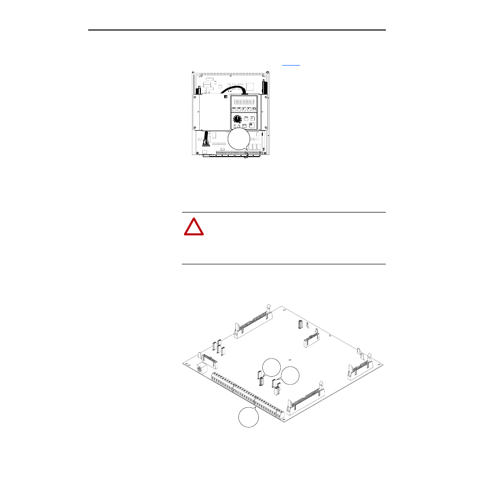
7. Route the card’s orange and black twisted cable underneath the drive
carrier to Regulator Board Terminal Block J3 as shown. Make
connections to J3 per the table on
Tachometer Wiring
Refer to the Cable & Wire Recommendations in the 1397 User Manual as
well as any tachometer wiring instructions included with the Reliance
tachometer.
Setup
(4) parameters as well as Jumpers J11 & J14 on the drive’s Regulator Board
are used to configure the AC Tachometer Interface Card.
Terminal
Block
J3
!
ATTENTION: Applying the incorrect polarity to the AC
Tachometer Interface Card’s orange & black J2 output wires can
cause an overspeed condition. Connect these wires accurately as
described in the Setup Section that follows. Failure to observe
this precaution could result in bodily injury and/or equipment
damage.
I/O
Terminal
Block
J3
Jumper
J11
Jumper
J14
J7
J17
AR
M 1
J24
J23
J25
J22
GR
OU
ND
AR
M 1
FB R
B
J18
J6
J28
J26
803
624
-093
A
AB
139
7
J2
J1
J5
1
2
3
4
5
6
7
8
9 10
11
12 13
14
15
16
17
18
19
20
21
22 23
24
25
26
27
28
29
30
31
32
MA
NUA
L
REF
J19
EXT
PO
T
TAC
H V
RA
NG
E
J14
HI
25
0 m
ax
LO
62 m
ax
VO
LTS
MA
MP
S
AUT
OR
EF
J12
SPE
ED
CU
RR
ENT
REG
ULA
TOR
TY
PE
J15
ENA
BLE
FIE
LD L
OSS
DET
ECT
J20
DIS
AB
LE
J16
OIM
PRO
GR
AM
ENA
BLE
DIS
AB
LE
J21
FIE
LD S
UPP
LY
JUM
PE
R
B-C
A-C
TAC
H V
SCA
LE
J11
62
/25
0
31
/12
5
16
PAR
K
10-50
(BO
TH)
J10
AUT
OR
EF
VO
LTS
4-
20
J3
J4
J27