Rockwell Automation 1492-CM800-LD003 Field Wire Conv. Module for Modicon B805-016 or B853-016 to 1756-IA16 User Manual
Page 3
(3)
10000021858
(Version 00)
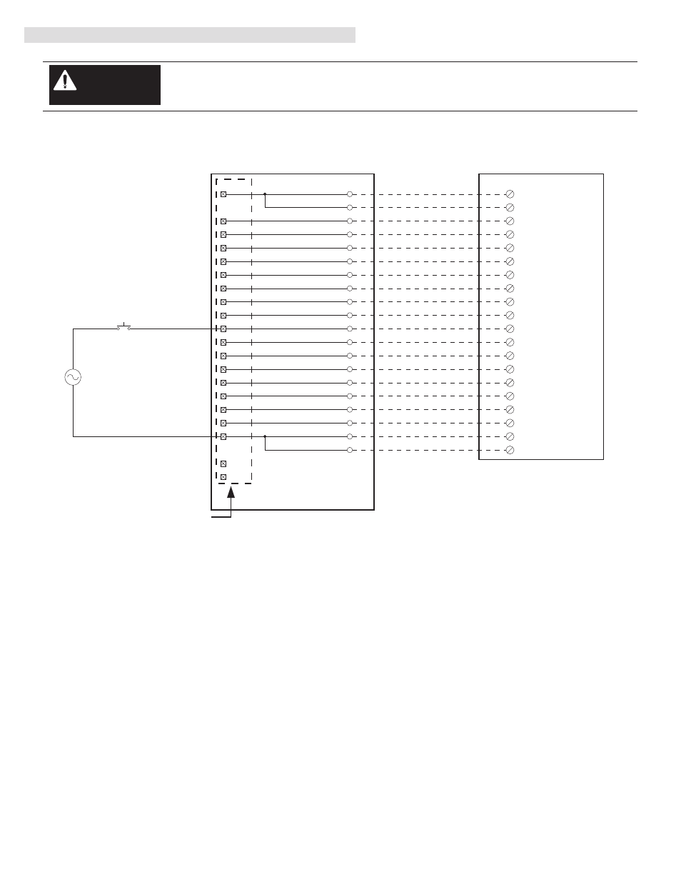
1492-CABLE003X
1492-CM800-LD003
1756-IA16
Conversion: B853-016 to 1756-IA16 with 1492-CM800-LD003
B853-016 Swing Arm
Conversion Module Installation and Application Considerations
The input delay times for the B853-016 module versus 1756-IA16 module are as follows:
B853-016
1756-IA16
a) Off-to-On Delay
6ms
10ms (plus selectable filter)
b) On-to-Off Delay
18ms
8ms (plus selectable filter)
Refer to your B853-016 and 1756-IA16 Installation Manual wiring schematics and diagrams for more details.
The B853-016 module is rated 115V AC or 125V DC. The 1756-IA16 is AC rated only.
[Reference Doc: 41170-765 (Version 03)]
IV. Conversion Module Wiring Diagram (Continued)
10
L2-0
IN-0
1
IN-1
2
IN-2
3
IN-3
4
IN-4
5
IN-5
6
IN-6
7
IN-7
8
IN-8
11
IN-9
12
IN-10
13
IN-11
14
IN-12
15
IN-13
16
IN-14
17
IN-15
18
Black
White
Red
Green
Orange
Blue
White/Black
Red/Black
Green/Black
Orange/Black
Blue/Black
Black/White
Red/White
Green/White
Blue/White
Black/Red
White/Red
Orange/Red
Blue/Red
Red/Green
L2-1
20
9
L2-0
19
L2-1
9
1
1
19
2
3
3
4
4
5
5
6
6
7
7
8
8
9
19
10
11
11
12
12
13
13
14
15
15
16
16
17
17
18
18
20
14
2
L1
L2
Input 13
Input 15
Input 14
Input 16
Input 5
Input 7
Input 6
Input 8
Input 1
Input 3
Input 2
Input 4
Input 9
Input 11
Input 10
Input 12
Neutral Grp 1
Neutral Grp 2
10
20
Not Used
Not Used
There are several key application considerations and system specifications (bottom of drawing) when
using these components (conversion module, cable and output module). Read and understand these
considerations before installation.
WARNING
1492-CM800-LD003 Conversion Module
De-energize and lockout any and all power to all I/O field devices connected to the Modicon 800 I/O
housing, and the power to the 800 I/O housing itself. Ensure all power is de-energized and locked out
to any device in the control cabinet where the conversion is to be performed. Ensure work is
performed by qualified personnel.
WARNING
Refer to conversion module Specifications Section: Maximum Operating Voltage
10
L2-0
IN-0
1
IN-1
2
IN-2
3
IN-3
4
IN-4
5
IN-5
6
IN-6
7
IN-7
8
IN-8
11
IN-9
12
IN-10
13
IN-11
14
IN-12
15
IN-13
16
IN-14
17
IN-15
18
Black
White
Red
Green
Orange
Blue
White/Black
Red/Black
Green/Black
Orange/Black
Blue/Black
Black/White
Red/White
Green/White
Blue/White
Black/Red
White/Red
Orange/Red
Blue/Red
Red/Green
L2-1
20
9
L2-0
19
L2-1
9
1
1
19
2
3
3
4
4
5
5
6
6
7
7
8
8
9
19
10
11
11
12
12
13
13
14
15
15
16
16
17
17
18
18
20
14
2
L1
L2
Input 13
Input 15
Input 14
Input 16
Input 5
Input 7
Input 6
Input 8
Input 1
Input 3
Input 2
Input 4
Input 9
Input 11
Input 10
Input 12
Neutral Grp 1
Neutral Grp 2
10
20
Not Used
Not Used