Physical dimensions, Panel/wall mounting – Rockwell Automation 1606-XLSBATBR1 Power Supply Reference Manual User Manual
Page 4
All parameters are specified at 25°C ambient and after a 5 minutes run-in time unless noted otherwise.
4
Rockwell Automation Publication 1606-RM037A-EN-P — April 2014
Bulletin 1606 Switched Mode Power Supplies
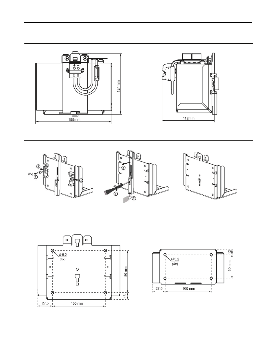
Physical Dimensions
Fig. 1 Front view
Fig. 2 Side view
Panel/Wall Mounting
Fig. 3 Detaching DIN rail brackets
Fig. 4 Detach slide
Fig. 5 Panel/wall mount
Detach the two aluminium brackets by
removing the two screws with a Torx
screwdriver (Torx 10).
Remove the plastic lock mechanism by
using a flat-blade screwdriver to press
the lock downwards while pushing the
plastic slide upwards at the same time.
Detach the plastic slide.
Panel/wall mounting is possible by
using either the four holes on the
rear or the bottom of the unit.
See hole pattern below.
Fig. 6 Rear hole pattern
Fig. 7 Bottom hole pattern