V. wiring diagrams (cont’d) – Rockwell Automation 1492-CM1771-LD0013F Field Wire Conversion Module User Manual
Page 6
PN-114285
DIR 10000060096 (Version 01)
Publication 1492-IN044B-EN-E
Printed in U.S.A.
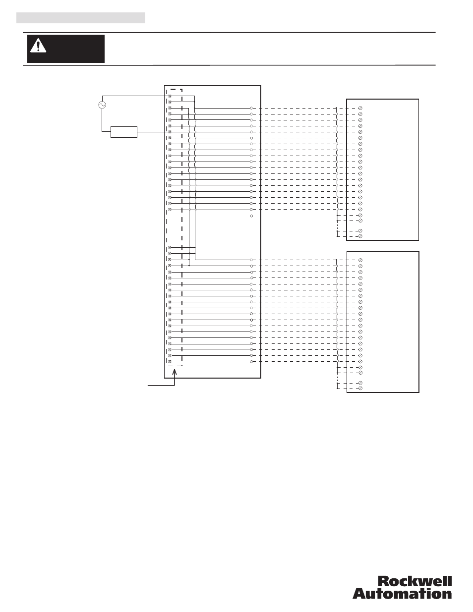
V. Wiring Diagrams (Cont’d)
There are several key application considerations and system specifications (bottom of drawing) when
using these components (conversion module, cable and input module). Read and understand these
considerations before installation.
WARNING
1771-WN Swing Arm
From 1771-OWNA
2
L1-0
L2-0
1
OUT-0
3
OUT-1
5
OUT-2
7
OUT-12
9
OUT-13
11
OUT-14
13
OUT-15
15
17
19
21
23
25
27
29
31
Black
White
Red
Green
Orange
Blue
White/Black
Red/Black
Green/Black
Orange/Black
Blue/Black
Black/White
Red/White
Green/White
Blue/White
Black/Red
White/Red
1
2
3
4
5
7
8
9
10
18
11
12
13
15
16
17
14
L1-1
OUT-3
4
L1-1
OUT-4
OUT-5
OUT-6
OUT-7
OUT-8
OUT-9
OUT-10
OUT-11
20
Red/Green
21
Orange/Green
22
Black/White/Red
24
Red/Black/White
25
Green/Black/White
26
Orange/Black/White
27
Blue/Black/White
28
Black/Red/Green
29
White/Red/Green
30
Red/Black/Green
31
Green/Black/Orange
32
Orange/Black/Green
33
Blue/White/Orange
34
Black/White/Orange
35
White/Red/Orange
36
White/Red/Blue
37
A
B
E
L
U
D
O
ME
L
U
D
O
M
30
20
2
40
4
3
6
5
8
7
12
9
34
13
1
16
15
18
17
22
19
24
23
26
25
28
27
32
29
11
33
10
L2
L2
L2
L2
Output 00
Output 01
Output 02
Output 03
Output 04
Output 05
Output 06
Output 07
Output 10
Output 11
Output 13
Output 15
Output 12
Output 17
L1
35
31
14
L1
21
L1
Output 14
Output 16
38
36
37
39
L1
Output 00
Output 01
Output 02
Output 03
Output 04
Output 05
Output 06
Output 07
Output 10
Output 11
Output 13
Output 15
Output 12
Output 17
Output 14
Output 16
Orange/Red
6
23
White/Black/Red
Orange/White/Blue
L1
L2
Output
Device
19
Blue/Red
L1-1
L1-1
6
32
34
2
L1-0
L2-0
1
OUT-0
3
OUT-1
5
OUT-2
7
OUT-12
9
OUT-13
11
OUT-14
13
OUT-15
15
17
19
21
23
25
27
29
31
L1-1
OUT-3
4
L1-1
OUT-4
OUT-5
OUT-6
OUT-7
OUT-8
OUT-9
OUT-10
OUT-11
L1-1
L1-1
6
32
34
Conversion: 1771-OWNA (1) to 1756-OW16I (2)
1756-OW16I
1756-OW16I
Conversion Module
1492-CM1771-LD013
Cable
1492-CONCAB005S4
Conversion Module Installation and Application Considerations
This Bul. 1492 cable consists of a cable wired to two 1756-OW16I RTB. Recommended cable lengths of 0.5M or 1.0M (005=0.5M, 010=1.0M).
See table 2 for other lengths.
The 1771-OWNA module output current limits versus 1756-OW16I limits are as follows:
1771-OWNA
1756-OW16I w/ 1492-CONCAB005S4
a)
Current/Point
1A
0.5A
b) Current/Module
12A (32 pts)
2A (16 pts)
The 1771-OWNA has 4 groups (allowing 4 separate power supplies). This module/cable combination ties all 4 groups from the 1771-OWNA
together. Field wiring modification must be made to accommodate this if mulitple supplies were used. If more than 1 supply was used, all but
1 of the power supplies must be removed.
The 1771-OWNA did not allow connections for L2, however the 1756-OW16I requires an L2 connection for proper operation. The 1771-OWNA
did not use terminals 10, 20, 30, 40. These terminals have been reassigned for an L2 connection in this application. The installer must rewire L2 to
one of these terminals.
Refer to your 1771-OWNA and 1756-OW16I Installation Manual wiring schematics and diagrams for more details. Ensure 1756 output module
ratings are not exceeded.
This configuration uses two (2) 1756-OW16I output modules to replace a single 1771-OWNA output module. This may require the use of a
larger 1756 I/O chassis and conversion mounting assembly. Ensure there is sufficient panel space to allow for this possibility.
1756-OW16I output modules has all inputs jumpered together pins 2 through 34 even.
[Reference Doc: 41171-019 (Version 00)]