Rockwell Automation 1492-IFMxxxx Sensor Interface Modules User Manual
Page 5
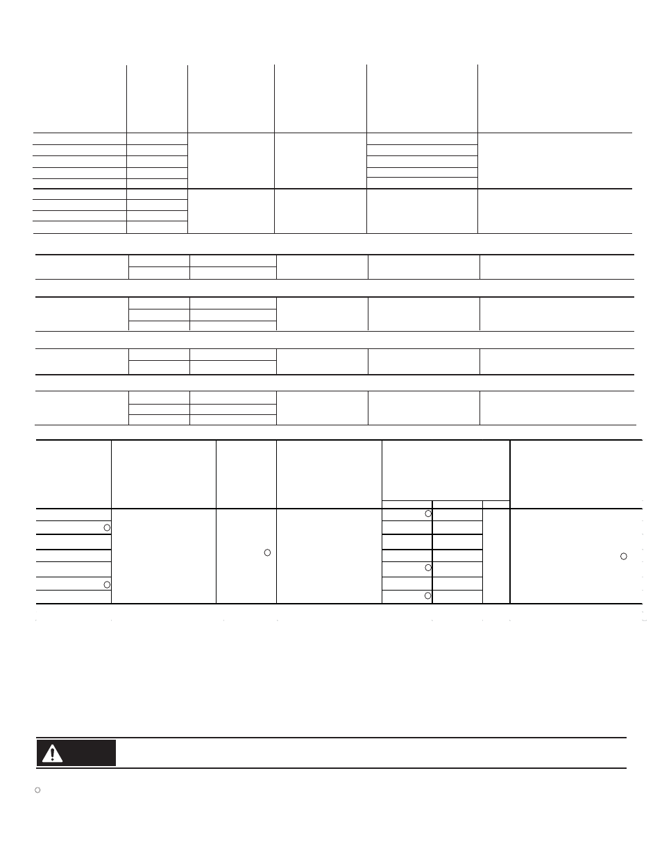
Specifications
Spécifications
Technische Daten
Specifiche
Especificaciones
1492-IFM20F, -RIFM20F
1492-IFM20D24
1492-IFM20D120
1492-IFM40F, -RIFM40F
1492-IFM40D24, -RIFM40D24
2 Amps
2 Amps
12 Amps
12 Amps
12 Amps
N/A
0-264 V AC/DC
10-30 V AC/DC
85-132 V AC/DC
0-132 V AC/DC
10-30 V AC/DC
0-132 VAC
10-125 VDC
N/A
2.0mA
2.5mA
N/A
2.0mA
1492-IFM20FH
1492-RIFM20FH
1492-IFM40FH
1492-RIFM40FH
0-132 V AC/DC
0-132 V AC/DC
0-132 V AC/DC
0-132 V AC/DC
N/A
Operating Temperature Range
Plage températures de fonctionnement
Betriebstemperaturbereich
Limiti temperatura di funzionamento
Rango de temperatura de funcionamient
Indicator Circuit Current
Courant circuit voyants
Strom, Anzeigeschaltkreis
Corrente circuito indicatori
Intensidad del circuito
de indicadores
Max. Current/Circuit
Max. Courant/Circuit
Max. Strom/Schaltkreis
Max. Corrente/circuito
Max. Intensidad/circuito
Max. Current/Module
Max. Courant/Module
Max. Strom/Modul
Max. Corrente/modulo
Max. Intensidad/módulo
Voltage Range
Tension
Spannung
Tensione
Voltaje
Catalog No.
Référence
Bestell-Nr.
N. Catalogo
Referencia
Dimensions
Dimensions
Abmessungen
Dimensioni
Dimensiones
Standards
Normes
Standards
Standard
Estándares
Operating Humidity
Humidité relative
Betriebsluftfeuchtigkeit
Umidità di esercizio
Humedad operativa
Catalog No.
Référence
Bestell-Nr.
N. Catalogo
Referencia
Ratings when used with 1762-L40AWA, 1762-L40BWA output. (For inputs use 2 Amps current per circuit.)
Ratings when used with 1762-L40BXB output. (For inputs use 2 Amps current per circuit.)
1492-IFM40F, -RIFM40F
Out 0 - 3, 2 Amps
Out 4 - 15, 1 Amp
12 Amps
N/A
0-264 VAC
10-125 VDC
Ratings when used with 1764-24AWA, 1762-24BWA output. (For inputs use 2 Amps current per circuit.)
1492-IFM20F, -RIFM20F
Out 0 - 3, 2 Amps
Out 4 - 11, 1 Amp
12 Amps
N/A
0-132 VAC
10-125 VDC
1492-IFM40F, -RIFM40F
Out 0, 1, 10, 11, 2 Amps
Out 12 - 15, 1 Amp
24 VDC
Out 2 - 9, 0.5 Amps
Ratings when used with 1764-28BXB output. (For inputs use 2 Amps current per circuit.)
12 Amps
N/A
0-264 VAC
10-125 VDC
1492-IFM20F, -RIFM20F
Out 0 - 1, 2 Amps
Out 8 - 11, 1 Amp
24 VDC
Out 2 - 7, 0.5 Amps
Maximum Recurring Peak Voltage
Tension de crele réurrente maximale
Maximale periodische Hochstspannung
Tensione massima di cresta ricorrente
Voltaje de cresta iterativo máximo
600 V
p
600 V
p
600 V
p
600 V
p
600 V
p
600 V
p
Approx. Shipping Weight
Poids d'embarquement approximatif
Ungefähres Versandgewicht
Peso approssimativo del carico
Peso aproximado al momento de
embarque
(5)
For transients > 600 Vp use a UL recognized suppression device rated at 2.5 kV withstand.
Pour des transitoires > 600 Vp utilisez un dispositif de suppression certifié UL à 2,5 kV nominal de tenue.
Für Einschaltstöße > 600 Vp verwenden Sie einen UL anerkannten Entstörer, der bewertet wurde bei 2,5 kV standzuhalten.
Per transitori > 600 Vp usare dispositivo di soppressione riconosciuto da UL capace di sopportare 2,5 kV.
Para transitorios > 600 Vp use un dispositivo de supresión reconocido UL clasificado con 2,5 kV.
Non-condensing
Sans condensation
Nicht kondensierend
Senza condensa
sin condensación
Power, input and output (I/O) wiring must be in accordance with Class I Division 2 wiring methods - Artticle 501-10(B)(1) of the National Electrical Code.
Add 0.39 in. to the width dimension for 1492-Rxx type modules.
WARNING
Explosion Hazard - substitution of components may impair suitability for Class I Division 2.
Explosion Hazard - Do Not Disconnect Equipment unless power has been switched off or the area is known to be Non-Hazardous.
PN-244749
DIR 40063-185 (Version 22)
Width
Height
Depth
1492-IFM20F, -RIFM20F
4.33 in. (110mm)
3.27 in. (83mm)
1492-IFM20FH, -RIFM20FH
4.72 in. (120mm)
2.78 in. (70.5mm)
1492-IFM20D24
4.33 in. (110mm)
3.27 in. (83mm)
1492-IFM20D120
4.33 in. (110mm)
3.27 in. (83mm)
1492-IFM40F, -RIFM40F
4.33 in. (110mm)
3.27 in. (83mm)
1492-IFM40FH, -RIFM40FH
4.72 in. (120mm)
2.78 in. (70.5mm)
1492-IFM40D24, -RIFM40D24
4.33 in. (110mm)
3.27 in. (83mm)
0° C - 60° C
5 - 95 %
0.62 lb.
(278 g.)
2.78 in.
(70.5mm)
cULus (File: E10314, Guide No. NRAG)
Suitable for use in Class 1 Div 2 Groups A, B, C and D
Hazardous and Non-Hazardous LocaƟons.
Temperature Code = T3C at 60°C
CE: Compliant for all applicable direcƟves
FM Class 1 Div 2 Groups A, B, C and D
Temperature RaƟng T3C = 60°C (J.I. 3000590)
3
4
5
5
5
6
6
6
No FM certification for this type of modules