Input connections – Rockwell Automation 1405-M610 Operating Instructions User Manual
Page 3
Publication 1405-IN001B-EN-P - October 2003
Bulletin 1405 (M610) Operating Instructions 3
Input Connections
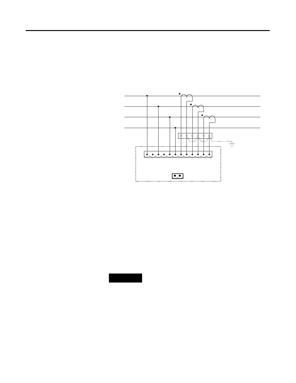
Input connections are at the rear, through a single 12-way plug-in
terminal block with spring clamps. The terminal block can accept wire
sizes from 28 to 14 AWG (0.08 to 2.5 mm
2
).
The module uses industry-standard current transformers with a 5A
secondary for line current measurement.
•
Internal shunt resistance for 5A current transformers: 0.01 ohm.
Aux Supply: With this option, instrument power is supplied by a
separate 120V or 240V line, independent of the measured power lines.
A second connector block (2-pin, spring-clamp terminals type) is
added at the rear with this option.
A unit with the 120V supply option is not designed to operate on
240V or any other voltage. Likewise, a unit with the 240V supply
option is not designed to operate on 120V or any other voltage. Units
designed for 400V and 480V operation do not have an auxiliary
supply connection and receive power from the measurement line.
Ensure that each unit is properly supplied with a power source that
matches the voltage designation of your unit.
TIP
Terminals 2 and 4 (counting from left to right) are
not used. No connections should be made to these
terminals.
M610
Gnd
(if req'd)
L1
L1
L2
L3
N
N
I1+
I1-
I2+
I2-
I3+
I3-
Shorting terminal block
(Wye connection optional)
L1
L2
L3
N