Installation of door hardware kits, Instructions, Allen-bradley – Rockwell Automation 1494F Flange Mounted Disconnect Switches Instructions User Manual
Page 7
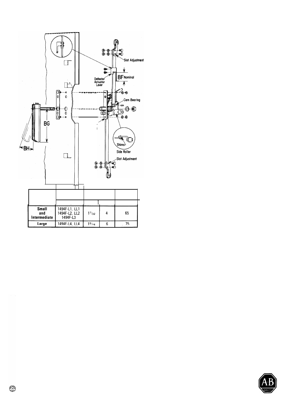
INSTALLATION OF DOOR HARDWARE KITS
Roller Assembly and Defeater Actuator Lever
1. Attach top roller assembly and bottom roller assem-
bly (when used) to the locking bar(s). A slotted hole
on roller assembly provides adjustment to insure
proper gasket sealing when enclosure dimensional
variations are encountered.
2. Fasten side roller assembly (when used) to the cam
plate using various shims supplied. Nominal enclo-
sure dimensions will require one (1)
1
/8
'' shim.
R u b b e r
S e a l i n g
Gasket
3. Attach the defeater actuator lever to the upper
locking bar. Refer to inset for assembled view as
seen from inside of enclosure. The two screws
should be located near the center of the adjustment
slot. Refer to Dimension "BF". Further adjustment
may be required after disconnect switch is installed.
Door Hardware Adjustments
NOTE: The following instructions are for a right-hand
flange installation. On a left-hand flange installation
substitute the words left for right, clockwise for coun-
terclockwise, and right for left as they appear.
With the disconnect secured to the flange in the “Off”
position and the door hardware attached to the door
proceed as follows:
Enclosure
Size
Hardware Dimensions
Kits in Inches
Catalog No. BF
BG
Degrees
B H
1.
Close enclosure door and slowly turn the handle to
the right (counterclockwise) until the first notch on
the cam plate is engaged. At this point positive
gasket seal should be obtained with proper roller
adjustment. When seal is obtained further adjust-
ment to the defeater actuator lever may be required
if the disconnect switch handle can be moved to the
“On” position.
I N S T R U C T I O N S
Locking Bar(s) and Handle Assembly
Using the roller latching arrangement to be installed
and the locking bar(s) prepared as specified on Page 6
proceed as follows:
1. Insert cam bearing(s) into the cam plate hole(s),
insert locking bar(s) in the cam bearing slot(s) and
secure by using the pin(s) provided. See above.
NOTE:
An alternate method requires using the
screw(s) and nut(s) also provided.
2. Remove door handle and cover plate from the
handle assembly. NOTE: Rubber sealing gasket
should not be removed from assembly.
3. Slide locking bar(s) attached to the cam assembly
through the slot in the guide bracket(s) located on
the enclosure door.
4. Insert cover plate studs through holes in door and
secure to cam assembly.
5. Replace handle.
NOTE:
An alternate method of assembly requires that
the handle assembly be installed first and then attach
locking bar(s) to the cam plate.
2. Rotate door handle further to the right. Relocate
defeater actuator lever if necessary, so that the
disconnect “On” position occurs well before the fully
latched (vertical) door handle position.
3. With the disconnect switch in the “Off” position, turn
recessed door defeater screw, hold and simultane-
ously turn handle to the left and pull. Door should
open.
4. Close door, turn door handle to fully latched position
and place disconnect switch in “On” position. Turn
recessed door defeater screw, hold and at the same
time turn door handle to the left and pull. Door
should open only partially. Maintain force on handle
and turn recessed defeater screw in cabinet flange.
The door should now open.
5. Close door and rotate door handle to the fully closed
position. Pull out handle padlocking bar. Insertion of
a
3
/16
"
minimum to
3
/ 8
" maximum shackle of a pad-
lock should prevent movement of the door handle.
NOTE:
Positive sealing and maximum safety have
now been attained.
ALLEN-BRADLEY
Milwaukee, Wisconsin 53204