Worldwide representation, Instructions 1336 plus control interface option – Rockwell Automation 1336S Control Interface Option User Manual
Page 2
Instructions
1336 PLUS Control Interface Option
Rockwell Automation helps its customers receive a superior return on their investment by bringing
together leading brands in industrial automation, creating a broad spectrum of easy-to-integrate
products. These are supported by local technical resources available worldwide, a global network
of system solutions providers, and the advanced technology resources of Rockwell.
Worldwide representation.
Argentina • Australia • Austria • Bahrain • Belgium • Bolivia • Brazil • Bulgaria • Canada • Chile • China, People’s Republic of • Colombia • Costa Rica • Croatia • Cyprus
Czech Republic • Denmark • Dominican Republic • Ecuador • Egypt • El Salvador • Finland • France • Germany • Ghana • Greece • Guatemala • Honduras • Hong Kong
Hungary • Iceland • India • Indonesia • Iran • Ireland • Israel • Italy • Jamaica • Japan • Jordan • Korea • Kuwait • Lebanon • Macau • Malaysia • Malta • Mexico
Morocco • The Netherlands • New Zealand • Nigeria • Norway • Oman • Pakistan • Panama • Peru • Philippines • Poland • Portugal • Puerto Rico • Qatar • Romania • Russia
Saudi Arabia • Singapore • Slovakia • Slovenia • South Africa, Republic of • Spain • Sweden • Switzerland • Taiwan • Thailand • Trinidad • Tunisia • Turkey • United Arab Emirates
United Kingdom • United States • Uruguay • Venezuela
Rockwell Automation Headquarters, 1201 South Second Street, Milwaukee, WI 53204-2496 USA, Tel: (1) 414 382-2000, Fax: (1) 414 382-4444
Publication 1336 PLUS-5.4 – June, 1994
P/N 74001-006-01 (B)
February, 1994
Copyright 1994, Allen-Bradley Company, Inc. Printed in U.S.A.
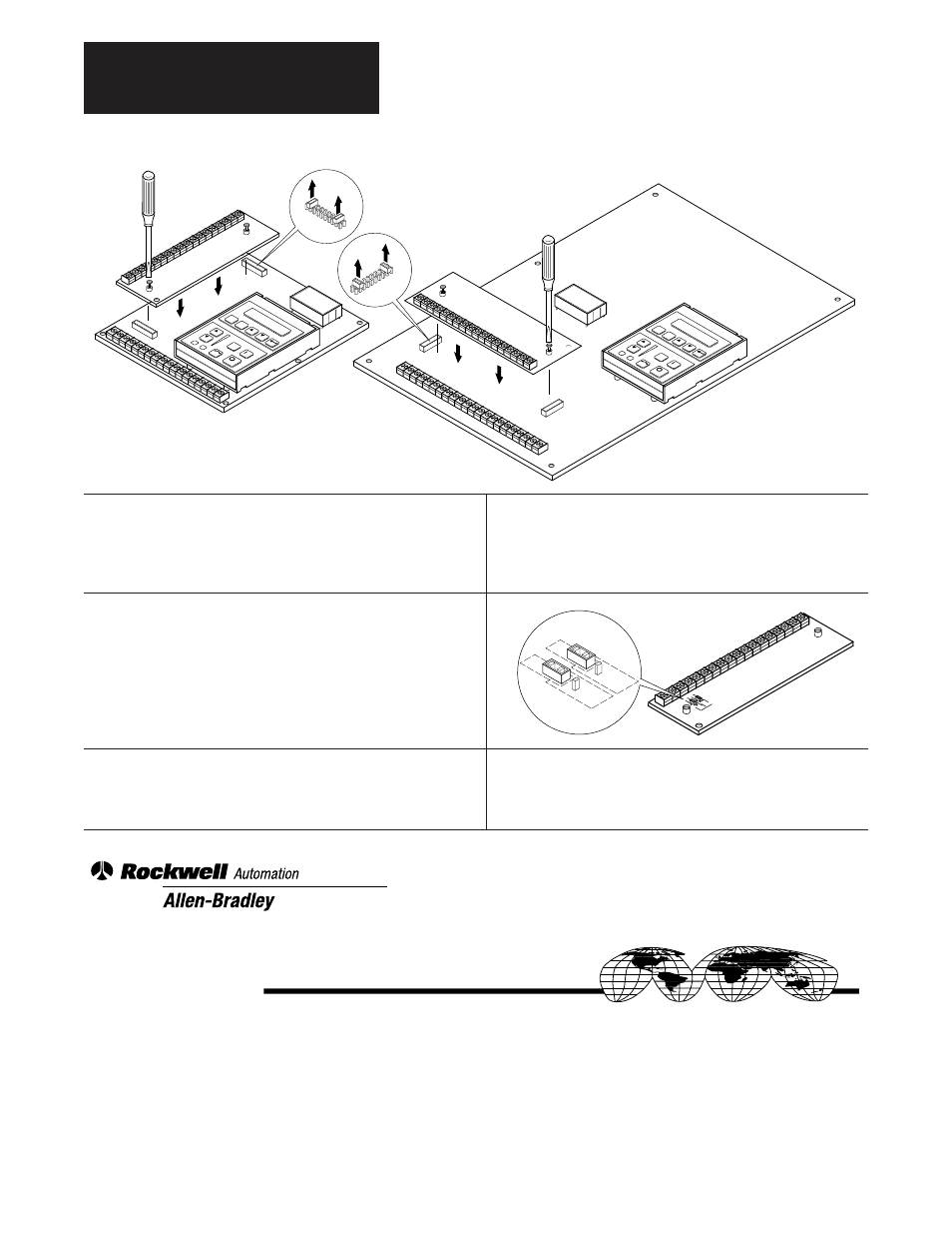
❏ 3. Carefully align the interface and control board
connectors. Firmly press the interface board on
to the Main Control Board until fully seated.
Tighten the 2 captive screws to secure the board.
❏ 4. If the L4E, L5E or L6E board is being installed,
JP3 and JP4 on the interface board must be set
to correspond with the encoder voltage being
used.
❏ 5. Perform wiring and program the appropriate
input mode as described in Chapter 2 of the 1336
PLUS User Manual. Replace drive cover.
LANG
UAGE
M
ODULE
ALL
EN
-BR
AD
LEY
LAN
GU
AGE
MO
DULE
ALLEN
-BRADLEY
0.37-3.7 kW (0.5-5 HP)
5.5-45 kW (7.5-60 HP)
JO
G
ES
C
SE
L
JO
G
ES
C
SE
L
1
1
2
2
3
3
J7
J4
5V
JP4
12V
5V
JP
3
12V
5V
JP4
12V
5V
JP3
12V
L4E, L5E, L6E Only