Install air flow switch, Air sampling connection – Rockwell Automation 1414-CPNxxxxx_CPMxxxxx Air Flow Switch User Manual
Page 3
Air Flow Switch 3
Publication 1414-IN003A-EN-P - October 2005
Install Air Flow Switch
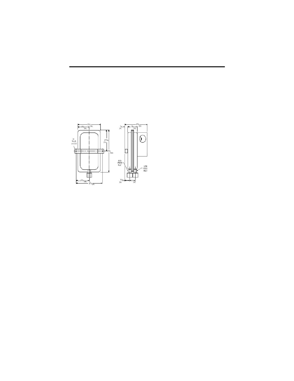
Select a mounting location which is free from vibration. The AFS pressure switch
MUST be mounted with the diaphragm in any vertical plane in order to obtain the
lowest specified operating set point. Avoid mounting with the sample line
connections in the “UP” position. Surface mount via the two 3/16” diameter holes in
the integral mounting bracket. The mounting holes are 3 7/8” apart.
Figure 1 Dimensions
Air Sampling Connection
The AFS is designed to accept sample lines of .25” OD tubing by means of ferrule
and nut compression connections. Locate the sampling probe a minimum of 1.5
duct diameters down stream from the air source. Install the sampling probe as close
to the air stream as possible. The low pressure side is designated by the stamped
‘LOW’ on the housing of the diaphragm.
• Positive Pressure Only: Connect the sample line to the LOW side and the
HIGH side remains open to atmosphere.
• Negative Pressure Only: Connect the sample line to the HIGH side and the
LOW side remains open to atmosphere.
• Two Negative Samples: Connect the higher negative sample to the HIGH
side and the lower negative sample to the LOW side.
• Two Positive Samples: Connect the higher positive sample to the LOW side
and the lower positive sample to the HIGH side.
• One Positive and One Negative Sample: Connect the positive sample to the
LOW side and connect the negative sample to the HIGH side.