Rockwell Automation 1606-XLE960 DC Power Supply User Manual
Page 4
1606-XLE960 Instruction Manual for Semi-regulated Power Supplies
1606-XLE960 Bedienungsanleitung für teilgeregelte Stromversorgungen
Terminals and Wiring
Do not use the unit without PE (Ground) connection! Use appropriate copper cables that are
designed for a minimum operating temperatures of 60°C (for ambient up to 45°C) and 75°C (for
ambient up to 60°C). Follow national installation codes and regulations! Ensure that all strands of a
stranded wire enter the terminal connection! Up to two stranded wires with the same cross section
are permitted in one connection point (except PE wire). Ferrules are allowed, but not required.
Input
Output
Solid wire
0.5-6mm
2
0.5-16mm
2
Stranded wire
0.5-4mm
2
0.5-10mm
2
American wire gauge
20-10 AWG
22-8 AWG
Wire stripping length
7mm / 0.28inch
12mm / 0.5inch
Recommended tightening torque
0.8Nm / 7lb.inch
1.2Nm / 10.6lb.inc
Anschlussklemmen und Verdrahtung
Betreiben Sie das Gerät nie ohne Schutzleiter. Verwenden Sie geeignete Kupferkabel, die
mindestens für 60°C bei einer Umgebungstemperatur bis zu 45°C und 75°C bei einer
Umgebungstemperatur bis zu 60°C zugelassen sind. Beachten Sie nationale Bestimmungen
und Installationsvorschriften! Stellen Sie sicher, dass keine einzelnen Drähte von Litzen
abstehen. Bis zu zwei Leiter mit gleichem Querschnitt sind in einem Anschlusspunkt zulässig
(außer für den Schutzleiter). Aderendhülsen sind erlaubt, aber nicht erforderlich.
g
n
a
g
s
u
A
g
n
a
g
n
i
E
Starrdraht
0.5-6mm
2
0.5-16mm
2
Litze
0.5-4mm
2
0.5-10mm
2
AWG
20-10 AWG
22-8 AWG
Abisolierlänge
7mm / 0.28inch
12mm / 0.5inch
Empfohlenes Anzugsmoment
0.8Nm / 7lb.inch
1.2Nm / 10.6lb.inch
Indicators and Reset Button
(see Fig. 6)
DC-ok LED (green): Indicates a normal operation. The LED is on if the output voltage is higher
than 90% of its nominal value.
Warning LED (yellow):
- A steady-state light indicates an output current higher than the nominal current
and that the internal shutdown timer is running.
- A double flash indicates a phase-loss or too low / too high input voltage.
- A fast flash warns of an impending temperature shut-down.
Shut-down LED (red) and reset button: The red lamp flashes when the device has shut down.
Pressing the reset button initiates a restart. If the fault has been cleared, the device will operate
normally.
Anzeigelampen und “Reset“ Taster
(siehe Bild 6)
“DC-ok” LED (grün): Zeigt einen fehlerfreien Betrieb und eine Ausgangsspannung größer
90% der Nennspannung an.
”Warning” LED (gelb):
- Dauerleuchten zeigt an, dass der Ausgangsstrom höher als der Nennstrom
ist und dass der interne Abschalt-Timer gestartet hat.
- Doppelblinken meldet Phasenausfall oder zu geringe / zu hohe Eingangsspannung.
- Ein schnelles Blinken kündigt eine mögliche Temperaturabschaltung an.
”Shut-down” LED (rot) und “Reset“ Taster: Die rote LED blinkt, wenn das Gerät
abgeschaltet hat. Das Drücken des Reset Tasters verursacht einen Startversuch. Ist
zwischenzeitlich der Fehler beseitigt worden, läuft das Gerät im Normalbetrieb weiter.
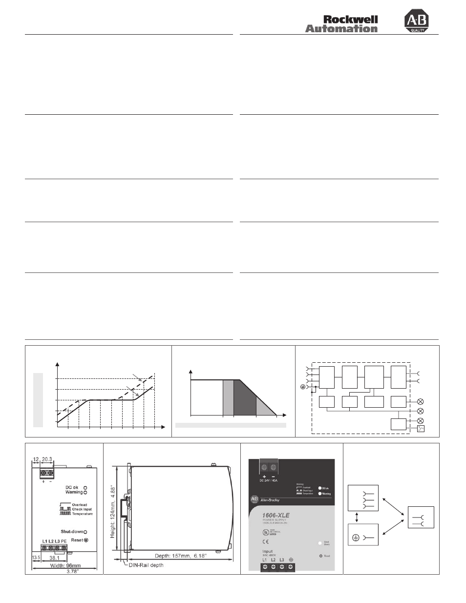
Input Voltage Range
(see Fig. 1)
Changes of the input voltage will provide a regulated output within certain limits. The output voltage
only changes proportionally to the input voltage under extreme under-voltages or over-voltages
conditions. The yellow LED reports an input voltage problem if the input voltage exceeds a window
of ±15%. The maximum increase of the output voltage is limited to the OVP level values (see table
on the page befre). The OVP level will be kept regulated for 2s. If this time has elapsed, the power
supply shuts-down and reports “Shut-down” by the red LED.
Eingangsspannungsbereich
(siehe Bild 1)
Innerhalb gewisser Grenzen werden die Änderungen der Eingangsspannung vollständig
ausgeregelt. Erst bei extremen Unter- bzw. Überspannungen beginnt die Ausgangsspannung
sich proportional zur Eingansspannung zu ändern. Außerhalb des ±15% Fensters meldet die
gelbe LED ein Problem mit der Eingangsspannung. Der Anstieg der Ausgangsspannung ist auf
den OVP Wert (siehe Tabelle auf der vorangegangenen Seite) begrenzt. Der OVP Wert wird für
2s gehalten, danach schaltet das Gerät ab und meldet „Shut-down“.
Output- and Overload Characteristic
(see Fig. 2)
The power supply responds with an automatic shut-down if the nominal output current is exceeded
for a certain period of time. Pressing the reset button or cycling the input power (10s required)
initiates an attempt to start. If the fault has been cleared, the device will operate normally. The
characteristics can be found in figure 3.
Zone A: 25% extra output power for typ. 15s
Zone B: 100% higher output current for typ. 5s
Zone C: Quick-acting shut-down after 0.1s
Ausgangs- und Überlastverhalten
(siehe Bild 2)
Wird der Nennstrom für eine bestimmte Zeit überschritten, schaltet das Gerät automatisch ab.
Ein Drücken des Reset Tasters oder ein Neustart des Gerätes (Wartezeit etwa 10s) erzeugt
einen Startversuch. Ist der Fehler behoben, läuft das Gerät wieder im Normalbetrieb weiter.
Das Verhalten ist im Bild 3 gezeigt.
Zone A: 25% mehr Ausgangsleistung für typ. 15s
Zone B: 100% höherer Ausgangsstrom für typ. 5s
Zone C: Schnellabschaltung nach 0,1s
Dielectric Strength
(see Fig. 7)
The output voltage is floating and separated from the input according to SELV (IEC/EN 60950-1)
and PELV (EN 60204-1, EN 50178; IEC 62103, IEC 60364-4-41) requirements. Type and factory
tests are conducted by the manufacturer. Field tests may be conducted in the field using the
appropriate test equipment which applies the voltage with a slow ramp (2s up and 2s down).
Connect all phase-terminals together as well as all output poles before the test is conducted.
A
B
C
Type Test
(60s)
2500Vac
3000Vac
500Vac
Factory Test (5s)
2500Vac
2500Vac
500Vac
Field Test
(5s)
2000Vac
2000Vac
500Vac
Isolationsfestigkeit
(siehe Bild 7)
Die Ausgangsspannung hat keinen Bezug zur Erde oder Schutzleiter und ist zum Eingang nach
den SELV (IEC/EN 60950-1) und PELV (EN 60204-1, EN 50178, IEC 62103, IEC 60364-4-41)
Standards getrennt. Typ- und Stückprüfungen werden beim Hersteller durchgeführt.
Wiederholungsprüfungen dürfen mittels geeigneten Prüfgenerators mit langsam (2s)
ansteigenden und abfallenden Spannungsrampen in der Anwendung erfolgen. Vor den Tests
sind alle Phasen wie auch alle Ausgangspole miteinander zu verbinden.
C
B
A
Typprüfung
(60s)
2500Vac
3000Vac
500Vac
Stückprüfung
(5s)
2500Vac
2500Vac
500Vac
Wiederholungsprüfung
(5s)
2000Vac
2000Vac
500Vac
Fig. 1 / Bild 1
Input voltage range / Eingangsspannungsbereich
Fig. 2 / Bild 2
Overload behaviour / Überlastverhalten
Fig. 3 / Bild 3
Functional Diagram / Funktionsschaltbild
24V
20V
26V
22V
504
456
576Vac
384
V
OUT
V
IN
480
28V
528 552
432
408
360
P
OUT
> 48W (5%)
56V
52V
48V
44V
40V
48V
24V
P
OUT
= 0W
V
OUT
40
50
115A
80
I
OUT
0
C
0.1s
B
5s
A
15s
24V:
48V:
20
25
58A
40
0
+
-
Active
Transient
Blocker
Input
Filter
Input
Rectifier
Reset
Output
Voltage
Monitor
Over-
Voltage
Protection
Output
Power
Manager
Temp.
Shut-
down
Input
Voltage
Monitor
L3
L2
L1
Semi-
regulated
Power
Converter
Output
Filter
DC-ok
lamp
Shut
down
Warning
lamp
Fig. 4 / Bild 4
Dimensions / Abmessungen
Fig. 5 / Bild 5
Dimensions / Abmessungen
Fig. 6 / Bild 6
Indicators / Anzeigeelemente
Fig. 7 / Bild 7
Isolation / Isolation
A
C
B
L1
Input
Earth
Output
-
+
L3
L2
10000044637
(version 00)
PU-353.010.39-10B