Rockwell Automation 900-TC32 Miniature Temperature Controller User Manual
Wiring operation menu, Other functions, Miniaturetemperature controller
1023125
H
A
B
C
D
E
F
G
1
2
3
4
5
6
7
8
REVISION
AUTHORIZATION
DIMENSIONS APPLY BEFORE
SURFACE TREATMENT
(DIMENSIONS IN INCHES)
TOLERANCES UNLESS
OTHERWISE SPECIFIED
REFERENCE
SHEET
OF
DWG.
B
DR.
CHKD.
APPD.
DATE
DATE
DATE
±
±
±
ANGLES:
.XXX:
.XX:
LOCATION : MILWAUKEE, WISCONSIN
U.S.A.
SIZE
PC DOCUMENT
G. Ushakow
M.A. Jutz
D. Schneider
6-7-06
6-7-06
6-7-06
1
6
41063-053
PRODUCT INSTRUCTION SHEET
DOCUMENT FOR 900-TC32
TEMPERATURE CONTROLLERS
5
N/A
N/A
N/A
41063
THIS DRAWING IS THE PROPERTY OF
ROCKWELL AUTOMATION, INC.
OR ITS SUBSIDIARIES AND MAY NOT BE COPIED,
USED OR DISCLOSED FOR ANY PURPOSE
EXCEPT AS AUTHORIZED IN WRITING BY
ROCKWELL AUTOMATION, INC.
1.00
0.0
Input type *2
Scaling upper limit
(only when setting analog input)
Scaling lower limit
(only when setting analog input)
Decimal point
(only when setting analog input)
C/ F selection
Set point upper limit
Set point lower limit
ON/OFF =
PID =
Standard control =
Heating and cooling control =
(Select standard control or heating
and cooling control as required)
Control period (OUT1)
(Unit: Seconds)
Control period (OUT2)
(Unit: Seconds)
Alarm 1 type: Specified models only
C=
F=
(C stands for Celsius, F for Fahrenheit)
Self-tuning ON =
Self-tuning OFF =
Direct operation =
Reverse operation =
*2
*3
Initial setting level enables users to specify their preferred operating
conditions (input type, alarm type, control method, etc.)
*2: Refer to the adjoining tables for details of input types and alarm types.
Up and Down keys
Use the keys to change the values displayed on
the No.2 display.
Each press of key increments or advances
the values displayed on the No.2 display.
Each press of key decrements or returns the
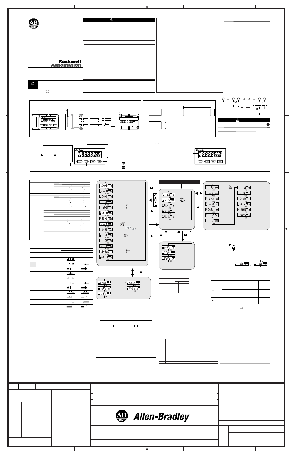
Connections
Wiring
Operation Menu
Installation
Dimensions
Operation indicators
CMW: "write" control by communications
Lights up when "write" is enabled; goes off when
"write" is disabled.
STP
Lights up when operation has stopped.
Lights up during control operation to indicate that
Run/Stop has been set to stop. Remains out at
all other times.
OUT
Lights up when Process control is on; goes out
when Process control is off
The indicator for the heating/cooling output indi-
cates that the output is set for heating OR cooling.
C / F Temperature Display
Used to indicate that the value in the dis-
play relates to temperature.
Determined in accordance with the chosen
"Temperature unit" setting.
f
= F
c
= C
This flashes while ST(Self-Tuning) is acti-
vated.
AL : Alarm
Lights up while alarm is operating function.
∗ Insert the main unit into through the mounting hole in the
panel (1-5 mm thickness). Push the adapter from the rear
up to the panel removing any gap between the controller,
panel and adapter.
Finally, secure the controller with screws.
Dimensions (mm)
(48 x number of units -2.5)
Individual mounting (mm)
Side-by-side mounting (mm)
Indicates information that, if not heeded, could result
in injury, damage to the product, or faulty operation.
Front Panel Description
No.1 display
Process value or set data symbol
No.2 display
Set point, set data read-out value or changed
input value
Display key
Press this key to change the contents of the
display
* Terminal part can be removed for maintenance without disconnecting the terminal wiring.
POWER ON
Operation level
Adjustment level
Protect level
Operation / Adjustment protect
The following table shows the relationship between settings
and protect limits related to Operation level and Adjustment level.
No protect when set to "0"
Default = "0"
A: Can be displayed or
changed
B: Can be displayed
C: Can not be displayed and
move to other levels not
possible
Process value
Set point
Others
Adjustment level
Mode
Setting
0
B
A
A
A
1
B
A
A
C
2
B
A
C
C
3
B
B
C
C
Setting change protect
Limits changes of setting by key operations.
OFF: Key operations can be used to change settings
ON : Key operations cannot be used to change settings
(Protect level settings can all be changed)
Initial / Communication protect
Limits transition to the Initial setting level, Communication setting
level and Advanced function setting level
Setting
0
1
2
Transition possible
(Transition to Advanced function
setting level possible)
Transition not possible
Transition possible
(Transition to Advanced function
setting level not possible)
Initial setting level
Communication setting level
Transition possible
Transition possible
Transition not possible
Initial setting level
For detailed operating instructions, please refer to
the 900-TC32 User's Manual(900-UM003B-EN-E).
It can be found online at
http://www.ab.com/manuals/.
Significance of WARNINGS and CAUTIONS
Alarms
*1: Upper and lower limits can be set for parameters 1, 4 and 5 to provide for
different types of alarm. These are indicated by the letter "L" and "H".
Default = "2"
Alarm type
1
0
2
3
4
5
6
7
8
9
10
11
Vary with "L", "H" values
Vary with "L", "H" values
Vary with "L", "H" values
No alarm function
Output off
Deviation upper/lower limit
standby sequence ON
Absolute value upper limit
Absolute value lower limit
Absolute value upper limit
standby sequence ON
Absolute value lower limit
standby sequence ON
Deviation lower limit
standby sequence ON
Deviation upper limit
standby sequence ON
Deviation upper/lower range
Deviation upper limit
Deviation upper/lower limit
Deviation lower limit
Alarm output function
Positive alarm value (X)
L H
L H
L H
ON
OFF
SP
Negative alarm value (X)
X
ON
OFF
SP
ON
OFF
SP
X
X
ON
OFF
SP
ON
OFF
SP
ON
OFF
SP
X
X
X
ON
OFF
SP
ON
OFF
SP
ON
OFF
SP
X
X
X
X
ON
OFF
SP
ON
OFF
SP
ON
OFF
0
ON
OFF
X
X
0
ON
OFF
0
ON
OFF
X
X
0
ON
OFF
0
ON
OFF
X
0
ON
OFF
0
ON
OFF
X
0
Setting
*1
*1
*1
Other functions
In addition to the aforementioned, there are alarm hysteresis,
automatic return of display mode and others in the advanced
setting level. Refer to "900-TC32 User's Manual" for details.
It can be found online at
http://www.ab.com/manuals/.
Shipped with product:
∗ Main unit
∗ Watertight gasket
∗ Adapter
∗ Instruction manual
control stopped
*6: Error shown only for "Process value / Set point". Not shown for other
status.
Error display (trouble shooting)
When an error has occurred, the No.1 display alternately indicates error
codes together with the current display item.
No.1 display
Meaning
A/D converter error
*6
Memory error
Input error
*6
(S. Err)
(E111)
Check the wiring of inputs, disconnections,
shorts and input type.
First, turn the power OFF then back ON again. If
the display remains the same, the controller must
be repaired. If the display is restored to normal,
then it is likely external noise affecting the control
system. Check for external noise.
After the correction of input error, turn the power
OFF then back ON again. If the display remains
the same, the controller must be repaired. If the
display is restored to normal, then a probable
cause can be external noise affecting the control
system. Check for external noise.
CAUTION
Action
Output status
Control
output
OFF
OFF
OFF
OFF
OFF
Alarm
output
1
2
3
4
5
6
7
8
9
TC
PT
A
B
A
B
B
+
_
(-)
(+)
+
_
_
+
RS-485
Communications
function
Voltage output
12V DC 21mA
Relay output
250V AC 2A
(resistive load)
Input power supply:
100 to 240V AC Type
24V AC/DC Type
OUT1
Analog input
ALM/OUT2
Alarm output
250V AC 1A
(resistive load)
48
24
35
CMW
OUT
STOP
900-TC32
22
.2
+0
.3
22
.2
+
0.
3
40
m
in
.
+1
45
+0.6
CMW
OUT
STOP
CMW
OUT
STOP
Adjustment level is the input mode for control and correction settings
AT execute =
AT cancel =
Communication write
*4
Temperature input shift
Input shift upper limit
(When Infrared Thermo-
sensor selected)
Input shift lower limit
(When Infrared Thermo-
sensor selected)
Proportional band
Derivative time
(Unit: secs)
Cooling coeficient
Dead band
Integral time
(Unit: secs)
Manual reset value
(Unit: %)
Hysteresis (OUT1)
Hysteresis (OUT2)
Operation level should normally be used
during operations. Process value can be
monitored.
PV/SP
Alarm value 1 *4
Alarm value upper limit 1
*3
Alarm value lower limit 1
*3
Run =
Stop =
Operation / adjustment
protect
Initial /
Communication
protect
Setting change protect
Key input cannot be used to modify
protected data settings.
Pr
es
s
(le
ss
th
an
1
s
ec
on
d)
Ho
ld
d
ow
n
fo
r a
t l
ea
st
3
se
co
nd
s
Ho
ld
d
ow
n
fo
r
at
le
as
t 1
s
ec
on
d
Hold and
keys down for
at least 3 seconds
*3: Applicable only to models with alarm functions
*4: Applicable only to models with a communications function
*5: Controller dose not operate during initial setting level.
(Process will be stopped)
Use the following key operations for transition between level:
Operation level Protect level: + keys for at least three seconds
Operation level Adjustment level: key for less than one second
Operation level Initial setting level: key for at least three seconds
The values of grayed out parameters are shown only when set.
AT (auto-tuning)
Communication
unit No.
Communication
rate
Data length
Stop bit
Parity
Make sure the communication settings (Communication rate, etc.)
match those of the host computer.
Communication setting level
Press
(less than 1 second)
STX
Node
No.
SID FINS-mini
Command text
ETX
Sub-
address
BCC
STX
Node No.
Sub-address
SID
FINS-mini
command text
ETX
BCC
Code (H'02) to indicate the head of the communication frame (text).
If STX is received a second time while receiving a communication, it
indicates that the communication is starting again from that point.
Specifies the transmission destination unit No. Settings range from
00 to 99.
"00" (Fixed)
Service ID, "0" (Fixed)
Contains command contents such as read and write values, and
status data
Code (H'03) indicating the end of the text.
Block check character
Error check method used by FINS-mini.
Each byte from node No. through ETX has an XOR (exclusive OR)
value
Command format
00
0F
10
11
12
13
14
16
18
Termina-
tion code
Name
Description
Normal termination
Command error
Parity error
Framing error
Overrun
BCC error
Format error
Sub-address error
Frame length error
Unexecutable command received
Parity mismatch
No stop bit detected
Receive buffer overflowed
BCC mismatch
Incorrect data length
Incorrect sub-address
When the receive frame exceeds the specified byte count
Termination code
AT for temperature adjustment
When AT is running, "on: AT excute".
To cancel AT, select "off: AT cancel".
"AT execute/cancel"
The display reads "OFF" after AT is finished
running.
∗ When more than one device is installed, make sure that the
ambient temperature does not exceed the specified limit.
*5
Direct operation: The manipulated variable is in-
creased in line with the increase in the PV.
Reverse operation: Reverse of Direct operation.
N
o.
1
di
sp
la
y
fla
sh
es
w
he
n
he
ld
d
ow
n
fo
r
m
or
e
th
an
1
s
ec
Level key
Use this key to change levels:
Press the key and the key together for
at least 3 seconds to switch to protect level.
*4
Default = "1"
44.8
36
.8
100
3
22
Waterproofing is not
possible with side-
by-side installation.
When waterproofing
is required, fit
watertight gasket on
the backside of front
panel.
Operates
as above
the upper
limit.
If the input value exceeds the display limit (-1999(-199.9) to 9999(999.9)),
though it is within the control range, will be displayed under
-1999(-199.9) and
]]]]
above 9999(999.9). Under these conditions, control
output and alarm output will operate normally.
Refer to "900-TC32 User's Manual" for details of control range.
Hold and
keys down for
at least 1 second
Model
900-TC32
MiniatureTemperature
Controller
41063-053-01 (5)
Printed In China
English
-200 to 850 ( C)
-199.9 to 500.0 ( C)
0.0 to 100.0 ( C)
-199.9 to 500.0 ( C)
0.0 to 100.0 ( C)
-300 to 1500
( F)
-199.9 to 900.0
( F)
0.0 to 210.0
( F)
-199.9 to 900.0
( F)
0.0 to 210.0
( F)
Setting range
Setting
0
1
2
3
4
Input type
Platinum
resistance
thermometer
Input
Pt100
JPt100
Pl
ati
nu
m
re
sis
tan
ce
the
rm
om
ete
r
inp
ut
typ
e
-200 to 1300 ( C)
-20.0 to 500.0 ( C)
-100 to 850 ( C)
-20.0 to 400.0 ( C)
-200 to 400 ( C)
-199.9 to 400.0 ( C)
0 to 600 ( C)
-100 to 850 ( C)
-200 to 400 ( C)
-199.9 to 400.0 ( C)
-200 to 1300 ( C)
0 to 1700 ( C)
0 to 1700 ( C)
100 to 1800 ( C)
0 to 90 ( C)
0 to 120 ( C)
0 to 165 ( C)
0 to 260 ( C)
-300 to 2300
( F)
0.0 to 900.0
( F)
-100 to 1500
( F)
0.0 to 750.0
( F)
-300 to 700
( F)
-199.9 to 700.0
( F)
0 to 1100
( F)
-100 to 1500
( F)
-300 to 700
( F)
-199.9 to 700.0
( F)
-300 to 2300
( F)
0 to 3000
( F)
0 to 3000
( F)
300 to 3200
( F)
0 to 190
( F)
0 to 240
( F)
0 to 320
( F)
0 to 500
( F)
Setting range
Setting
0
1
2
3
4
17
5
6
7
18
8
9
10
11
12
13
14
15
16
Input type
Thermocouple
Infrared
Thermosensor
Analog input
Input
K
J
T
E
L
U
N
R
S
B
10 - 70 °C
60 - 120 °C
115 - 165 °C
160 -- 260 °C
0 to 50mV
Use the following ranges for scaling:
-1999 to 9999, -199.9 to 999.9, Vary
Depending on "L", "H" value
Th
er
m
oc
ou
pl
e
in
pu
t t
yp
e
Default="0" (both of input types)
Input type
Type of Control
[[[[
Allen-Bradley Company, LLC
Industrial Components Business
1201 South Second Street
Milwaukee, WI 53204-2496 USA
Phone 440.646.5800
Rockwell Automation
CH-5001 Aarau, Switzerland
FAX ++41.62.837.2202
CAUTION
Devices are Open Type, Listed Process Control Equipment and must be mounted in
an enclosure.
More than one disconnect switch may be required to de-energize the equipment
before servicing.
Signal inputs are SELV, limited energy.
Caution - To reduce risk of fire or Electrical shock, Do not interconnect the outputs of
different Class 2 circuits.
Disconect power to device before installing or servicing.
Do not touch the terminals of controller when voltage is applied.
Do not allow metal fragments or lead wire scraps to fall inside this product. This may
cause electric shock, fire or malfunction.
Do not use this product where subject to flammable or explosive gas.
Never disassemble, repair or modify the product.
The life expectancy of the output relays varies greatly with the switching capacity and
other switching conditions. Always use the output relays within their rated load and
electrical life expectancy. If an output relay is used beyond its life expectancy, its
contacts may become fused or burned.
Use copper stranded or solid wire only. For terminals 1-6 use 24-14 AWG. For
terminals 7-9 use 28-22 AWG. Tightening torque: Terminals 1-6: 0.24N∗m, 2 inch lbs
(max), Terminals 7-9: 0.13N∗m, 1.2 inch lbs(max) Loose screws may cause
malfunction. Only two wires of same type and size per terminal.
Correctly set the temperature controller settings to match the control target. If the
settings are not compatible with the control target, the product may operate in an
unexpected manner, resulting in damage to the product or an accident.
To maintain safety in the event of malfunction of the temperature controller, we
recommend taking safety measures, for example, installing an excessive temperature
rise prevention alarm on a separate line. If malfunction prevents control, this may
result in a major accident.
(1) Do not use this product in the following:
∗ Places directly subject to heat radiated from heating equipment.
∗ Places subject to splashing liquid or oil atmosphere (exceeds NEMA 4X).
∗ Places subject to direct sunlight, could discolor or cause excessive heat.
∗ Places subject to dust or corrosive gas (in particular, sulfide gas and
ammonia gas).
∗ Places where intense temperature changes exceed the published ratings.
∗ Places subject to icing and condensation.
∗ Places subject to vibration and large shocks.
(2) Use/store within the rated temperature and humidity ranges.
Provide forced-cooling if required.
(3) To allow heat to escape, do not block the area around the product.
Do not block the ventilation holes on the product.
(4) Be sure to wire properly with correct polarity of terminals.
(5) Use AWG24 to AWG14 leads for terminal Nos. 1 to 6 and AWG28 to AWG
22 for terminal Nos. 7 to 9 (with lead cover peel back allowance of 5 or 6 mm).
(6) Do not wire the terminals which are not used.
(7) Allow as much space as possible between the controller and devices that
generate a powerful high-frequency or surge.
Separate the high-voltage or large-current power lines from other lines, and
avoid parallel or common wiring with the power lines when you are wiring to
the terminals.
(8) Use this product within the rated load and power supply.
(9) Make sure that the rated voltage is attained within two seconds of turning the
power ON.
(10) When executing self-tuning, turn the load and the unit ON simultaneously,
or turn the load ON before you turn the controller ON.
(11) A switch or circuit breaker should be provided close to this unit.
The switch or circuit breaker should be within easy reach of the operator,
and must be marked as a disconnecting means for this unit.
(12) If you remove the controller from its case, or put the controller into its case,
never touch nor apply shock to the terminals and the electronic parts inside.
Make sure the electronic components and the case are not contacted when
inserting the internal mechanism.
(13) Cleaning: Do not use paint thinner or the equivalent. Use standard grade
alcohol to clean the outside of the product.
NOTICE
When the product is used under the circumstances or environment below, ensure adherence to
limitations of the ratings and functions. Also, take countermeasures for safety precautions such
as fail-safe installations.
∗ Use under circumstances or environment which are not described in the instruction manual.
∗ Use for applications where death or serious property damage is possible and extensive safety
precautions are required.
Specifications 900-TC32
Power supply voltage
Operating frequency
Operating voltage range
Power consumption
Sensor input
Control output
Mechanical life of relay
Electrical life of relay
Control method
Ambient temperature
Ambient humidity
Storage temperature
Recommended fuse
Vibration resistance
Shock Resistance
Weight
Installation environment
100-240VAC type
24VAC/DC type
50-60Hz
85 to 110% of the rated voltage
7VA (AC100-240V)
4VA (AC24V), 2.5W (DC24V)
Thermocouple,
platinum resistance thermometer,
analog input,
Infrared Thermosensor
Relay/Voltage Output
10 million operations
100,000 operations
ON/OFF or advanced PID
-10 to 55 ¡C (Non-condensing)
RH 25 to 85%
-25 to 65 ¡C (Non-condensing)
T2A, 250V AC, time-lag,
low-breaking capacity
10 to 55Hz, 10 m/s
2
(1G),
2 hrs each all 3 axis
300 m/s
2
(30G), 3 times for all 3
axis (relay: 100 m/s
2
(10G))
Approx. 90g (main unit only)
Installation Category II, pollution
degree 2(as per IEC61010-1)
1617528-0A
900-TC32
900-TC32
R6
CAUTION
WARNING: To reduce the risk of electric shock or fire, install in
Pollution Degree 2 environment (a controlled environment relatively
free of contaminates).
Power supply, input, output, and communication terminals (for models with
communications) have basic insulation between them.
When double insulation is required, apply supplemental insulation defined in
IEC 60664 that is suitable for the maximum operating voltage with clearances
or solid insulation.
Conformity to Safety Standards (Connections, To conform to
IEC/EN Standards)
*To avoid grouped loops, only ground one of the control terminals.