V. wiring diagrams (continued) – Rockwell Automation 1492-CM1771-LD001 Digital I/O Conversion Module User Manual
Page 5
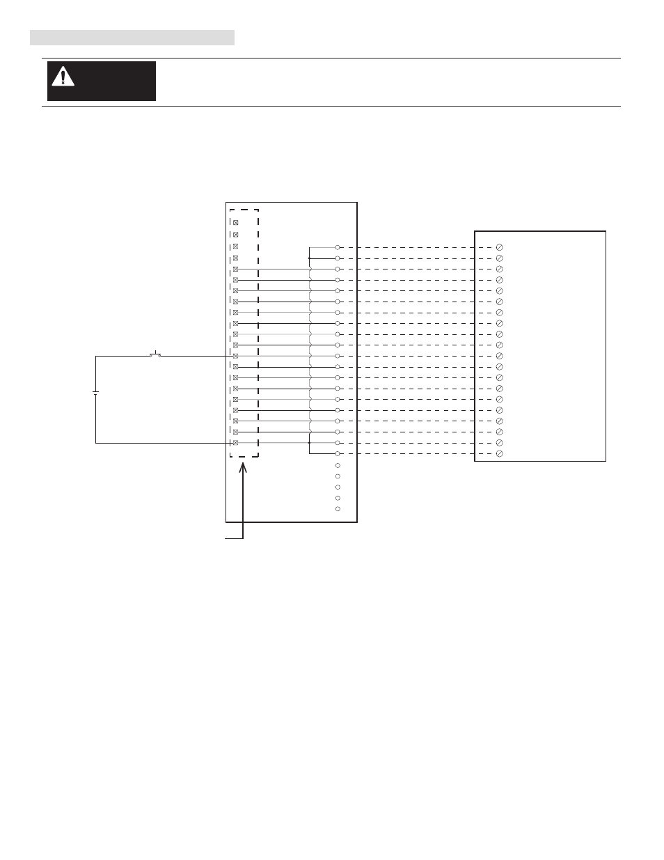
V. Wiring Diagrams (Continued)
1756-IB16
10
GND-0
IN-0
1
IN-1
2
IN-2
3
IN-3
4
IN-4
5
IN-5
6
IN-6
7
IN-7
8
IN-8
11
IN-9
12
IN-10
13
IN-11
14
IN-12
15
IN-13
16
IN-14
17
IN-15
18
Black
White
Red
Green
Orange
Blue
White/Black
Red/Black
Green/Black
Orange/Black
Blue/Black
Black/White
Red/White
Green/White
Blue/White
Black/Red
White/Red
Orange/Red
Blue/Red
Red/Green
GND-1
20
9
GND-0
19
GND-1
A
1
00
19
01
3
02
4
03
5
04
6
05
7
06
8
07
9
E
10
11
10
12
11
13
12
13
15
14
16
15
17
16
17
18
20
14
2
Input 14
Input 16
Input 15
Input 17
Input 04
Input 06
Input 05
Input 07
Input 00
Input 02
Input 01
Input 03
Input 10
Input 12
Input 11
Input 13
Terminal A
Terminal E
B
C
D
Terminal B
Terminal C
Terminal D
+
-
24
21
22
23
25
Conversion Module Installation and Application Considerations
This Bul. 1492 cable consists of a cable wired to one 1756-IB16 RTB. Recommended cable lengths of 0.5M or
1.0M (005=0.5M, 010=1.0M). See table 2 for other lengths.
The input delay times for the 1771-IBD module versus the 1756-IB16 module are as follows:
1771-IBD
1756-IB16 w/ 1492-CONCAB005X
a) Off-to-On Delay
1ms
1ms (plus selectable filter)
b) On-to-Off Delay
1ms
2ms (plus selectable filter)
Refer to your 1771-IBD and 1756-IB16 Installation Manual wiring Schematics and diagrams for more details.
[Reference Doc: 41170-926 (Version 02)]
1771-WH Swing Arm
From 1771-IBD
(5)
There are several key application considerations and system specifications (bottom of drawing) when
using these components (conversion module, cable and input module). Read and understand these
considerations before installation.
WARNING
Conversion: 1771-IBD to 1756-IB16
PN-114270
DIR 10000060084 (Version 01)
Publication 1492-IN035B-EN-E
Conversion Module
1492-CM1771-LD001
Cable
1492-CONCAB005X