Row b tb1 row a, Cn tb2 row b tb2 row a – Rockwell Automation 1492-XIMTRxxx_RXIMTRxxx 16 and 32 Point Relay Interface Modules User Manual
Page 3
PN-91272
DIR 10000083677 (Version 02)
Publication 1492-IN052C-MU-E
(3)
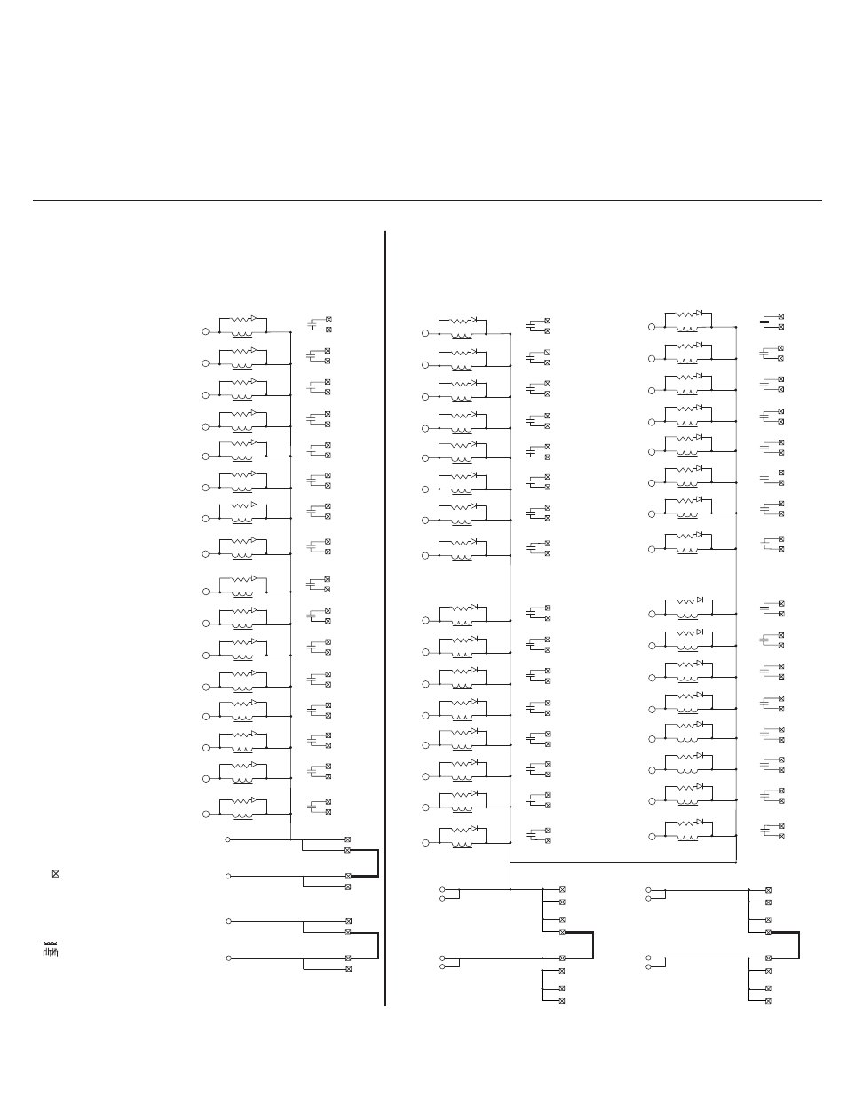
1492-XIMTR2024-16R
1492-RXIMTR2024-16R
Pinout
Brochage
Anschlußbelegung
Disposizione dei piedini
Esquema de pins
I/O Wiring Data
1492-XIMTR4024-32R
1492-RXIMTR4024-32R
= Field-side Terminal
= Borne extérieure
= Feldseitiger Terminal
= Terminale lato-campo
= Terminal de campo
= Relay
= Relasi
= Relasi
= Relay
= Relés
3
4
5
K0
K1
K2
K3
K4
K5
K6
K7
6
7
8
9
A16
10
A17
A18
CN
~~
~~
~~
~~
~~
~~
~~
~~
TB1
11
12
13
K8
K9
K10
K11
K12
K13
K14
K15
14
15
16
17
18
~~
~~
~~
~~
~~
~~
~~
~~
5
7
9
K0
K1
K2
K3
K4
K5
K6
K7
A7
A8
A5
A6
11
A9
A10
13
A11
A12
15
A13
A14
17
A15
A16
19
A17
A18
CN
~~
~~
~~
~~
~~
~~
~~
~~
A3
A4
21
23
25
K8
K9
K10
K11
K12
K13
K14
K15
27
29
31
33
35
~~
~~
~~
~~
~~
~~
~~
~~
TB1
6
8
10
K16
K17
K18
K19
K20
K21
K22
K23
12
14
16
18
20
~~
~~
~~
~~
~~
~~
~~
~~
22
24
26
K24
K25
K26
K27
K28
K29
K30
K31
28
30
32
34
36
~~
~~
~~
~~
~~
~~
~~
A7
A5
A6
A3
A4
A8
A9
A10
A11
A12
A13
A14
A15
B7
B8
B5
B6
B9
B10
B11
B12
B13
B14
B15
B16
B17
B18
B3
B4
A7
A8
A5
A6
A9
A10
A11
A12
A13
A14
A15
A16
A17
A18
A3
A4
B7
B8
B5
B6
B9
B10
B11
B12
B13
B14
B15
B16
B17
B18
B3
B4
B7
B8
B5
B6
B9
B10
B11
B12
B13
B14
B15
B16
B17
B18
B3
B4
ROW B
TB1
ROW A
~~
CN
TB2
ROW B
TB2
ROW A
IMPORTANT:
Wiring information for your I/O module, XIM module and cable (e.g. wiring diagram and pinouts)are available online at www.rockwellautomation.com/en/e-tools.
To obtain information follow this procedure.
1) In the Catalog Number BOX at the above online site type in the catalog number of the XIM, RXIM etc. module you are using and click on Submit.
2) At the next screen displayed, click on the Modify key (lower left of screen).
3) Click on the areas that indicate NO SELECTION and enter your specific configuration information (e.g. I/O platform, I/O MODULE, ETC.).
NOTE: To obtain the wiring diagram, you must select the Pre-Wired Cable Connector selection.
4) Configure your 1492 cable by filing in the NO SELECTION areas.
5) Click on the ACCEPT key for the configured 1492 cable. At the next screen click on ACCEPT for the 1492 module.
6) The next screen (Configuration Results) displays the results of your specific configuration. The "supplementary Documents" column contains I/O wiring
information for the configuration (e.g. I/O Wiring Diagrams).
B19
A19
40
37
38
39
B1
A1
4
1
2
3
B2
B20
TB1
B19
B20
TB2
A20
TB1
A19
A20
TB2
TB1
TB2
TB1
TB2
B1
B2
A2
A1
A2
COM
DC (+)
User installed jumper
User installed jumper
B1
1
A1
19
TB1
B2
A2
B19
2
B20
A19
20
COM
DC (+)
A20
User installed jumper
User installed jumper