Rockwell Automation 1336S PLUS to PLUSII Upgrade Inst. User Manual
Page 3
Upgrading the 1336 PLUS AC Drive to a 1336 PLUS II
3
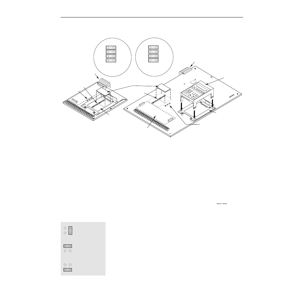
Figure 2
Installing the New Main Control Board
12. If Analog I/O Option Boards (LA1, LA2, etc.) are going to be used, they
should be installed at this time using the instructions included with the
option.
13. If analog options are not used or only one option board has been installed,
the Main Control Board must be configured to utilize the Standard Analog
I/O.
A. A series of jumpers are used to connect the standard I/O to TB2 when
analog options (LA1, LA2, etc.) are not present. Connectors J9 and
J10 (see Figure 2) each have four jumpers connecting pins 1-2, 3-4,
5-6 and 7-8. These jumpers must be in place for the inputs and
outputs to be active at TB2.
Important:
Note that jumpers for inputs 0, 1 and 2 are not located in
logical order on the board.
Important:
If only one analog option has been installed, the
remaining slot must have the jumpers installed.
B. Each input (Input 0, 1, 2) can be configured for 0-10V, 0-20 mA or
potentiometer. Placing a jumper across the top of the connector (J8,
J11, J13) configures that input for 0-10V operation (see diagram).
The bottom provides 0-20 mA and the right-side provides
potentiometer operation. Factory default for all three are 0-10V.
14. A Frame Drives Only – Locate the clear plastic terminal guard (supplied).
Remove the protective strip and place the guard over the bottom two
mounting feet of the cradle. Press the guard onto the back of the cradle.
15. Install the new cradle using the four screws supplied.
Control Interface Option
Location
ANALOG I/O
SLO
T B
8
6
4
2
7
5
3
1
J10
ANALOG I/O
SLO
T A
8
6
7
5
3
1
J9
POWER
SUPPLY
RUN
STOP
FAULT
POWER
SUPPLY
RUN
STOP
FAULT
ANALOG I/O
SLO
T B
8
6
4
2
7
5
3
1
J10
ANALOG I/O
SLO
T A
8
6
7
5
3
1
J9
JOG
ESC
SEL
Connector J9
Connector J10
J8, J11, J13
TB2-4
Common
TB2-3
Input 1
TB2-2
Input 0
TB2-1
Pot Ref. (5V)
TB2-9
Common
TB2-8
Output 1
TB2-7
Output 0
TB2-6
Input 2
Text Does Not Appear on Board
(for explanation purposes only)
Remaining Pins
Not Shown
Text Does Not Appear on Board
(for explanation purposes only)
Remaining Pins
Not Shown
Analog Option Board
(Slot A)
Ribbon Cable Connector
Ribbon Cable Connector
J9, J10
J9, J10
Slot B
J8, J11, J13
HIM Cradle
HIM
Frames A1 - A4
IP 00 (Open) & IP 20 (NEMA Type 1)
Frames B - G, IP 00 (Open)
Frames B - C, IP 20 (NEMA Type 1)
0-10V
J13 (TB2-3, Input 1)
(Pot Configuration Shown)
0-20 mA
Po
t
P
ot
Po
t
0-10V
J8 (TB2-2, Input 0)
(0-10V Configuration Shown)
0-20 mA
0-10V
J11 (TB2-6, Input 2)
(0-20 mA Configuration Shown)
0-20 mA
Standard Analog I/O Jumpers