Rockwell Automation 900-TC16NCOM_TC16NEIM_TC16NACCO_TC16NACEIM_TC16NCOMP3_TCNCOMV2_TC16P1V Temperature Controller Option Units User Manual
Rockwell Automation Equipment
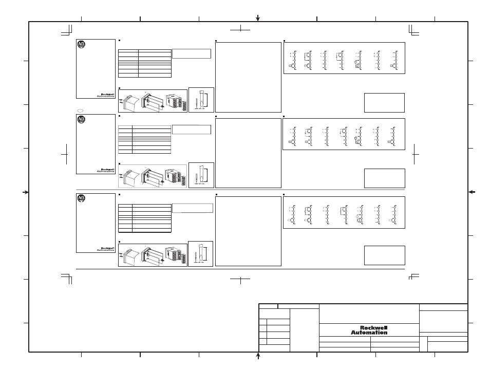
Contents of box
Assembling the unit
• Option units
• Terminal block, 1
• Terminal labels, 1 sheet
(1) Insert the tools (see drawing below) into
the slots (one at the top and one at the
bottom) and release the hooks.
(2) Grip the sides of the front panel firmly
and pull forward to remove it.
(3) Match up the upper and lower claws
with the connection points and insert the
board.
(4) Attach the terminal block included with
the Option unit to the outer case.
(5) Make sure the watertight packing is in
place, then press the outer casing into
position. Listen for the click.
Standard slot screwdriver
(unit: mm)
0.4
2.0
20 min.
Handle with care. Do not touch the
electronic parts and do not jolt the
unit.
1618402-5B
Make sure the box contains the following items. If anything is missing or damaged, contact your dealer im-
mediately.
CN9
0.4
2.0
Lieferumfang
Stellen Sie sicher, daß der Karton die folgenden Artikel enthält. Wenn Teile fehlen oder beschädigt sind,
wenden Sie sich an Ihren Fachhändler.
• Optionseinheiten
• Klemmenleiste, 1
• Klemmenaufkleber, 1
Montage der Einheit
Vorsichtig behandeln. Keine elek-
tronische Teile berühren, und das
Gerät nicht Stö ßen aussetzen.
(1) Die Werkzeuge (unten gezeigt) in die Schächte
einstecken (einer oben und einer unten), und
die Haken lösen.
(2) Die Seiten der Frontplatte fest greifen, und zum
Entfernen nach vorne ziehen.
(3) Die oberen und unteren Klauen mit angehobe-
nen Anschlußpunkten ansetzen und die Platte
einsetzen.
(4) Verbinden Sie den Klemmenblock der Option
Unit mit dem äußeren Gehäuse.
(5) Sicherstellen, daß die wasserdichte Packung
vorhanden ist, und dann das Außengehäuse in
Position eindrücken. Bis zum hörbaren Klickger-
äusch eindrücken.
Schraubenzieher
(Einheit: mm)
• Einzelheiten zur Bedienung siehe 900-TC16 Anwenderhandbuch.
• Einzelheiten über Kommunikationsspezikationen siehe Bulletin 900
Kommunikation-Anwenderhandbuch.
20 min.
0.4
2.0
Contenu du carton
Assurez-vous que le carton contient les éléments suivants. Si l'un d'entre eux manque ou est endom-
magé, contactez immédiatement votre fournisseur.
• Unités optionnelles
Assemblage de l'unité
• Bornier, 1
• Etiquette des bornes, 1
Manipulez avec soin. Ne touchez
pas les pièces électroniques et ne
secouez pas l'unité.
(1) Introduisez les outils (voyez le dessin ci-des-
sous) dans les fentes (une en haut et une en
bas) et relâchez les crochets.
(2) Empoignez fermement les côtés du panneau ant-
érieur et tirez celui-ci en avant pour le retirer.
(3) Faites correspondre les griffes supérieures et inf-
érieures aux points de jonction et insérez le ta-
bleau.
(4) Fixez le bornier inclus avec l'unité optionnelle au
boîtier extérieur.
(5) Assurez-vous que le sachet d'étanchéité est en
place puis remontez le panneau extérieur jus-
qu'à ce que vous entendiez un déclic.
Tournevis à fente standard (unité: mm)
• Pour des instructions détaillées sur les opérations, veuillez consulter
le manuel d'utilisation.
• Pour de plus amples détails sur les caractéristiques des
communications, 900-TC16 référez-vous au manuel d'utilisation des
communications du Bulletin 900.
20 min.
Model
Function
900-TC16NCOM
900-TC16NEIM
900-TC16NACCOM
900-TC16NACEIM
900-TC16NCOMP3
900-TCNCOMV2
900-TC16P1V2
900-TC16NCOM
900-TC16NEIM
900-TC16NACCOM
900-TC16NACEIM
900-TC16NCOMP3
900-TCNCOMV2
900-TC16P1V2
Communication (RS-485)
Heater burnout alarm, 1 alarm (CT)
Event inputs, 2 inputs
Heater burnout alarm, 1 alarm (CT)
Communication (RS-485)
Event inputs, 2 inputs
Communication (RS-485)
Heater burnout alarms, 2 alarms (CTs)
Communication (RS-485)
Control output 2 (voltage outputs)
Control output 2 (voltage outputs)
Heater burnout alarm, 1 alarm (CT)
Specifications
Connections
Apply the adhesive terminal label of the option unit to the side of the Temperature Controller.
Use separately available CTs: 900-CT1(Hole diameter: 5.8 mm) or 900-CT3(Hole diameter: 12 mm).
• For detailed operating instructions, please refer to
the 900-TC16 User's Manual.
• For details of the communication specifications, refer to
the Bulletin 900 Communications User's manual.
Kommunikationseinheit Schnittstelle: RS-485
Synchronisation: Start-Stopp (asynchron)
Kommunikation:
Halb-Duplex
Kommunikationsrate: 1.2/2.4/4.8/9.6/19.2/38.4 kbps
Ereigniseingang Kontakteingang:
EIN: 1 k max., AUS: 100 k min.
Kontaktloser
Eingang
EIN: Restspannung: 1.5 V max.
AUS: Leckstrom 0.1 mA max.
Alarm Ausbrennen Heizung Max. Heizungsstrom: 50 A AC
(Alarm Kurzschluss
Heizung) max.
Genauigkeit der Eingangsspannungsanzeige:
±5% FS ±1 Stelle max.
Einstellbereich für den Alarm für das Ausbrennen der
Heizung: 0,1 bis 49,9 A, in 0.1 A-Inkrementen
(Einstellbereich für Alarm für Heizungskurzschluss)
Erkennung EIN Zeit (Erkennung AUS Zeit): 190 ms
Hinweis: Die Werte in Klammern beziehen sich auf die
Alarmeinstellung für Heizungskurzschluss.
Regelausgang 2
Spannungsausgang: 12 VDC, 21 mA
(mit
Kurzschlussschutz)
Technische Daten
Connections
Bringen Sie die selbstklebende Klemmenbeschriftung der Option Unit an der Seite des Temperaturreglers an.
Getrennt erhältliche CTs verwenden: 900-CT1(Lochdurchmesser: 5,8 mm) oder 900-CT3(Lochdurchmesser: 12 mm).
Communication Interface: RS-485
Synchronisation: MARCHE/ARRET (asynchrone)
Communication: semi-duplex
Vitesse de communication:1.2/2.4/4.8/9.6/19.2/38.4 Ko/s
Entrée événement
Entrée avec contact
En fonction: 1k max., hors fonction: 100k min.
Entrée sans contact
En fonction: tension résiduelle 1.5V max.
Hors fonction: courant de fuite 0.1mA max.
Alarme de dysfonctionnement Courant maximal de l’élément chauffant : CA 50 A
de l’élément chauffant Précision de l'indication du courant d'entrée : ± 5 % FS ± 1 chiffre max.
(alarme Heater Short)
max.
Plage de réglage de l'alarme de dysfonctionnement
de l’élément chauffant : de 0,1 à 49,9 A, par
incrément de 0,1 A
(Plage de réglage de l'alarme HS)
Temps d'activation de la détection
(temps de désactivation de la détection): 190 ms
Note : Les valeurs entre parenthèses concernent le réglage
de l'alarme Heater Short.
Sortie de contrôle 2
Sortie de tension : 12 Vc.c., 21 mA
(avec une protection de court-circuit)
Caractéristiques techniques
Connexions
Collez l'étiquette adhésive des bornes de l'unité optionnelle sur le côté de la commande de température.
Utilisez séparément les CT disponibles: 900-CT1(Diamètre du trou : 5,8 mm) ou 900-CT3(Diamètre du trou : 12 mm).
Modèle
Fonction
900-TC16NCOM
900-TC16NEIM
900-TC16NACCOM
900-TC16NACEIM
900-TC16NCOMP3
900-TCNCOMV2
900-TC16P1V2
communication (RS-485)
Alarme de dysfonctionnement de l’élément chauffant, 1 alarme (TC)
Entrées événements, 2 entrées
Alarme de dysfonctionnement de l’élément chauffant, 1 alarme (TC)
communication (RS-485)
Entrées événements, 2 entrées
communication (RS-485)
Alarmes de dysfonctionnement de l’élément chauffant, 2 alarmes (TC)
communication (RS-485)
Sortie de contrôle 2 (sorties de tension)
Sortie de contrôle 2 (sorties de tension)
Alarme de dysfonctionnement de l’élément chauffant, 1 alarme (TC)
Communication Interface:
RS-485
Synchronization: Start-stop (asynchronous)
Communication: Half duplex
Communication rate: 1.2/2.4/4.8/9.6/19.2/38.4 kbps
Event input
Contact input
ON: 1k max., OFF: 100k min.
Non-Contact
input
ON: residual voltage 1.5V max.
OFF: leakage current 0.1mA max.
Heater burnout alarm Maximum heater current: 50 A AC
(Heater Short alarm)
Input current indication accuracy: ±5% FS ±1 digit
max.
Heater burnout alarm setting range: 0.1 to 49.9 A,
in 0.1 A increments
(Heater Short alarm setting range
Detection ON time (detection OFF time) : 190 ms
Note: Values in parentheses apply to the Heater Short
alarm setting.
Control output 2
Voltage output: 12 VDC, 21 mA
(with short-circuit protection circuit)
CT1
900-TC16P1V2
Control Output 2/
CT
12
11
15
14
13
900-TC16NCOMV2
Communications/
Control Output 2
B
A
RS-485
12
11
15
14
13
900-TC16NCOMP3
Communications/
CT2
CT2
CT1
13
14
15
11
12
B
A
RS-485
900-TC16NACCOM
Communication
DO NOT
USE
DO NOT
USE
DO NOT
USE
DO NOT
USE
DO NOT
USE
B
A
RS-485
12
11
15
14
13
900-TC16NACEIM
Event input
EV1
EV2
12
11
15
14
13
900-TC16NEIM
Event input /
CT
CT1
13
14
15
11
12
EV2
EV1
900-TC16NCOM
Communication /
CT
CT1
13
14
15
11
12
B
A
RS-485
DO
NOT
USE
DO
NOT
USE
DO
NOT
USE
Control Output 2
Control Output 2
Control
output 2
·
Voltage
outputs
DC12V
21mA
+
-
+
-
Allen-Bradley Company, LLC
Industrial Components Business
1201 South Second Street
Milwaukee, WI 53204-2496 USA
Phone 440.646.5800
Rockwell Automation
CH-5001 Aarau, Switzerland
FAX ++41.62.837.2202
CT1
900-TC16P1V2
Regelausgang 2/
Stromwandler
12
11
15
14
13
900-TC16NCOMV2
Kommunikationen/
Regelausgang 2
B
A
RS-485
12
11
15
14
13
900-TC16NCOMP3
Kommunikationen/
Stromwandler 2
CT2
CT1
13
14
15
11
12
B
A
RS-485
900-TC16NACCOM
Kommunikationen
B
A
RS-485
12
11
15
14
13
900-TC16NACEIM
Ereigniseingänge
EV1
EV2
12
11
15
14
13
900-TC16NEIM
Ereigniseingänge /
Stromwandler
CT1
13
14
15
11
12
EV2
EV1
900-TC16NCOM
Kommunikationen/
Stromwandler
CT1
13
14
15
11
12
B
A
RS-485
Nicht
verwenden
Nicht
verwenden
Nicht
verwenden
Nicht
verwenden
Nicht
verwenden
Nicht
verwenden
Nicht
verwenden
Nicht
verwenden
Regelausgang 2
Regelausgang 2
Regelausgang 2
·
Spannungsausgang:
12 VDC, 21 mA
+
-
+
-
CT1
900-TC16P1V2
Sortie de contrôle 2/
CT
12
11
15
14
13
900-TC16NCOMV2
Communications/
Sortie de contrôle 2
B
A
RS-485
12
11
15
14
13
900-TC16NCOMP3
Communications/
CT2
CT2
CT1
13
14
15
11
12
B
A
RS-485
900-TC16NACCOM
Communication
Ne pas
utiliser
Ne pas
utiliser
Ne pas
utiliser
Ne pas
utiliser
Ne pas
utiliser
B
A
RS-485
12
11
15
14
13
900-TC16NACEIM
Entrées
événements
EV1
EV2
12
11
15
14
13
900-TC16NEIM
Entrées
événements / CT
CT1
13
14
15
11
12
EV2
EV1
900-TC16NCOM
Communication /
CT
CT1
13
14
15
11
12
B
A
RS-485
Ne pas
utiliser
Ne pas
utiliser
Ne pas
utiliser
Sortie de
contrôle 2
Sortie de
contrôle 2
Sortie de
contrôle 2
·
Voltage
outputs
DC12V
21mA
+
-
+
-
Allen-Bradley Company, LLC
Industrial Components Business
1201 South Second Street
Milwaukee, WI 53204-2496 USA
Phone 440.646.5800
Rockwell Automation
CH-5001 Aarau, Switzerland
FAX ++41.62.837.2202
Allen-Bradley Company, LLC
Industrial Components Business
1201 South Second Street
Milwaukee, WI 53204-2496 USA
Phone 440.646.5800
Rockwell Automation
CH-5001 Aarau, Switzerland
FAX ++41.62.837.2202
Temperature Controller
Option Units
900-TC16NCOM
900-TC16NEIM
900-TC16NACCOM
900-TC16NACEIM
900-TC16NCOMP3
900-TCNCOMV2
900-TC16P1V
English
41063-223-01 (2)
Printed In China
For detailed operating instructions, please
refer to the 900-TC16 User's Manual.
It can be found online at:
http://www.ab.com/manuals/.
Temperatur-Steuergerät
Optionseinheiten
900-TC16NCOM
900-TC16NEIM
900-TC16NACCOM
900-TC16NACEIM
900-TC16NCOMP3
900-TCNCOMV2
900-TC16P1V2
German
41063-223-01 (2)
Printed In China
For detailed operating instructions, please
refer to the 900-TC16 User's Manual.
It can be found online at:
http://www.ab.com/manuals/.
Contrôleur de température
Unités optionnelles
900-TC16NCOM
900-TC16NEIM
900-TC16NACCOM
900-TC16NACEIM
900-TC16NCOMP3
900-TCNCOMV2
900-TC16P1V2
French
41063-223-01 (2)
Printed In China
For detailed operating instructions, please
refer to the 900-TC16 User's Manual.
It can be found online at:
http://www.ab.com/manuals/.
FORM 981
A
B
C
D
E
F
H
G
1
2
3
4
5
6
7
8
1
2
TEMPERATURE CONTROLLER
OPTION UNITS
INSTRUCTION SHEET
1
1015641
2
1023125
G. Ushakow
6-9-06
M. Jutz
6-9-06
D. Schneider
6-9-06
41063-223
OF
.XX
.XXX
XX
REVISION
AUTHORIZATION
DR.
CHKD.
APPD.
DATE
DATE
DATE
E - DOC
LOCATION: MILWAUKEE, WISCONSIN U.S.A.
DWG.
SIZE
SHEET
C
REFERENCE
DIMENSIONS APPLY BEFORE
SURFACE TREATMENT
(DIMENSIONS IN INCHES)
TOLERANCES UNLESS
OTHERWISE SPECIFIED
.XX:
.XXX:
ANGLES:
41063
THIS DRAWING IS THE PROPERTY OF
ROCKWELL AUTOMATION, INC.
OR ITS SUBSIDIARIES AND MAY NOT BE COPIED,
USED OR DISCLOSED FOR ANY PURPOSE
EXCEPT AS AUTHORIZED IN WRITING BY
ROCKWELL AUTOMATION, INC.
C-horizontal.ai
Watertight packing
Wasserdichte Packung
Emballage étanche
Modell
Funktion
Kommunikation (RS-485)
Alarm für das Ausbrennen der Heizung, 1 Alarm (Stromwandler)
Ereigniseingänge, 2 Eingänge
Alarm für das Ausbrennen der Heizung, 1 Alarm (Stromwandler)
Kommunikation (RS-485)
Ereigniseingänge, 2 Eingänge
Kommunikation (RS-485)
Alarme für das Ausbrennen der Heizung, 2 Alarme (Stromwandler)
Kommunikation (RS-485)
Regelausgang 2 (Spannungsausgabe)
Regelausgang 2 (Spannungsausgabe)
Alarm für das Ausbrennen der Heizung, 1 Alarm (Stromwandler)
(1)
(5)
(2)
(1)
(3)
(4)
(1)
(5)
(2)
(1)
(3)
(4)
(1)
(5)
(2)
(1)
(3)
(4)