Rockwell Automation 1485 PowerTap Connection User Manual
Page 2
Publication 75006–280–01(B)
September 2000
Printed in USA
Visit our web site at:
http://www.ab.com/sensors
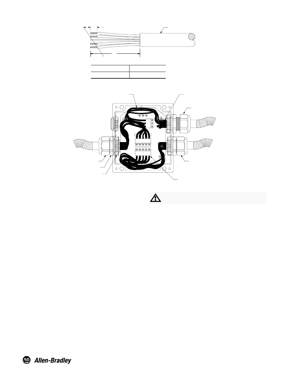
Figure 3: Cable Stripping Installation for PowerTap Connection
5/16
A
Cable Jacket
Dimension A"
Trunk Cable
4 inches
Trunk Cable
4 inches
Figure 4:
Loosened
Gland Nut
Tightened
Gland Nut
Align Wire End with Clamping
Cavity of Terminal Block
Gland Nut
Hex Flange
Locking Nut
End of Cable Jacket Should
Protrude Approx. 1/8 in.
Input from
Power Supply
1. To install trunk cable into PowerTap connection cut and
strip gray PVC cable back approximately 4 inches (see
Figure 3) and insert through large cable gland. Note:
Trunk cable used for input from power supply should have
white and blue leads cut off short.
2. Loosen gland nut and insert cable until approximately 1/8
inch of cable jacket protrudes.
3. Firmly tighten gland nut to provide strain relief and sealing.
Caution: The hex flange must be held with the cable gland
wrench during tightening.
4. Bare wire ends should be firmly twisted to eliminate loose
strands and each lead looped approximately as shown, to
allow insertion into the clamping cavity of the terminal
block. (See Figure 2 for color codes.)
ATTENTION: Be certain to use insulating tubing
(included in accessory kit) on bare drain wire.
5. To attach cable to terminal strips, press down on cage
clamp, insert wire and release cage clamp. Repeat
process for remaining wires.
6. After all cables are terminated, the cover should be
installed and securely tightened to ensure washdown
rating.
All external wiring must conform to national electric code and
local codes.