Iv. conversion module wiring diagram, Module a module b – Rockwell Automation 1492-CM800-LD004 Field Wire Conv. Module for Modicon B806-032 to 1756-OA16 User Manual
Page 2
(2)
10000021863
(Version 00)
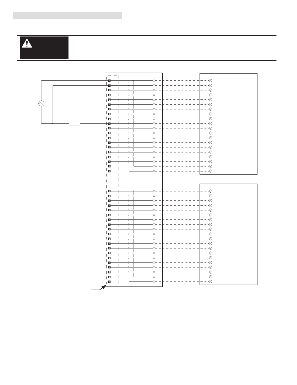
IV. Conversion Module Wiring Diagram
The following diagram shows the connections from the existing B806-032 swing-arm, through the conversion module, 1492
cables and to the 1756-OA16 output modules. The diagram can be used as an aid in possible system troubleshooting.
1756-OA16
1756-OA16
1492-ACABLE003X
1492-ACABLE003X
1492-CM800-LD004
Conversion: B806-032 to 1756-OA16 Qty 2 with 1492-CM800-LD004
B806-032 Swing Arm
1
2
3
4
3
5
22
6
4
7
23
8
5
9
24
10
6
11
25
12
7
13
26
8
15
27
16
9
17
28
18
10
19
29
20
14
12
31
13
32
14
33
15
34
16
35
17
36
18
37
19
38
21
11
Output 1
Output 17
Output 2
Output 18
Output 3
Output 19
Output 4
Output 20
Output 5
Output 21
Output 6
Output 22
Output 7
Output 23
Output 8
Output 24
Output 9
Output 25
Output 10
Output 26
Output 11
Output 27
Output 12
Output 28
Output 13
Output 29
Output 14
Output 30
Output 15
Output 31
Output 16
Output 32
39
20
2
Grp 1 Neut
40
1
30
Not Used
Grp 1 Hot
Not Used
1
2
3
4
5
6
7
8
9
10
11
12
13
15
16
17
18
19
20
14
MODULE
A
MODULE B
P1
P2
10
L1-0
OUT-0
1
OUT-1
2
OUT-2
3
OUT-3
4
OUT-4
5
OUT-5
6
OUT-6
7
OUT-7
8
OUT-8
11
OUT-9
12
OUT-10
13
OUT-11
14
OUT-12
15
OUT-13
16
OUT-14
17
OUT-15
18
Black
White
Red
Green
Orange
Blue
White/Black
Red/Black
Green/Black
Orange/Black
Blue/Black
Black/White
Red/White
Green/White
Blue/White
Black/Red
White/Red
Orange/Red
Blue/Red
Red/Green
L1-1
20
9
L2-0
19
L2-1
Grp 2 Neut
Not Used
Grp 2 Hot
Not Used
LOAD
L2
L1
Conversion Module Installation and Application Considerations
This configuration uses two (2) 1756-OA16 output modules to replace a single B806-032 output module. This may require the use
of a larger 1756 I/O Chassis. Ensure there is sufficient panel space to allow for this possibility.
The B806-032 module output current limits versus 1756-OA16 limits are as follows:
B806-032
1756-OA16 w/ 1492-CABLE003X
a) Current/Point
1A
0.5A
b) Current/Group
8A
2A
c) Current/Module
16A (32 pts)
4A (16 pts)
d) Surge Current/Pt 15A for 1 cycle
5A for 43ms
The B806-032 module did NOT provide fusing. The 1756-OA16 provides a single fuse per group.
The 1492-CABLE003X current is limited to 2A per pin.
Refer to your B806-032 and 1756-OA Installation Manual wiring schematics and diagrams for more details. Ensure 1756 output
module ratings are not exceeded.
[Reference Doc: 41170-753 (Version 03)]
There are several key application considerations and system specifications (bottom of drawing) when
using these components (conversion module, cable and output module). Read and understand these
considerations before installation. In addition, refer to the current draw requirements of the existing
loads for this configuration to ensure they are within the current ratings of the 1756 output module.
WARNING
1492-CM800-LD004 Conversion Module
De-energize and lockout any and all power to all I/O field devices connected to the Modicon 800 I/O
housing, and the power to the 800 I/O housing itself. Ensure all power is de-energized and locked out to
any device in the control cabinet where the conversion is to be performed. Ensure work is performed by
qualified personnel.
WARNING
Refer to conversion module Specifications Section: Maximum Operating Voltage