Rockwell Automation 1102C-COx93_DOx93 Vacuum Contactor (400A / 600A) User Manual
Page 5
42052-080
G. Ushakow
N/A
N/A
N/A
42052
1006490
1
INSTRUCTION SHEET
BULLETIN 1102C VACUUM CONTACTOR
CURRENT RATINGS 400A AND 600A
200V-1500V
2-20-04
Mark Jutz
2-20-04
D. Josef
2-20-04
5
9
REVISION
AUTHORIZATION
DIMENSIONS APPLY BEFORE
SURFACE TREATMENT
H
A
B
C
D
E
F
G
(DIMENSIONS IN INCHES)
TOLERANCES UNLESS
OTHERWISE SPECIFIED
REFERENCE
SHEET
OF
DWG.
B
DR.
CHKD.
APPD.
DATE
DATE
DATE
±
±
±
ANGLES:
.XXX:
.XX:
THIS DRAWING IS THE PROPERTY OF
THE ALLEN-BRADLEY CO. INC.
AND MAY NOT BE COPIED, USED OR
DISCLOSED FOR ANY PURPOSE EXCEPT
AS AUTHORIZED IN WRITING BY
THE ALLEN-BRADLEY CO. INC.
LOCATION : MILWAUKEE,
WISCONSIN
U.S.A.
SIZE
1
2
3
4
5
6
7
8
E - DOC
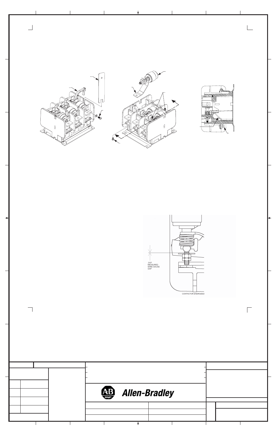
FIGURE 6A
FIGURE 6B
Contact Life over Travel Measurement
The purpose of this measurement is to determine how much vacuum interrupter electrical life remains on the contact and is performed using a
standard wire gauge in a "go, no go" check.
1. De-energize the contactor and isolate from all power sources. The control source can be maintained if coming from a separate supply or if
taken from a line to line connection by application then an additional control source needs to be connected to terminals A1 and A2. Re-
energize the contactor insuring that the main power circuits are open and isolated.
2. Remove Phase Cover as described (Figure 3A) page 2, earlier to access inspection area (Figure 7).
FIGURE 7
(5)
Vacuum Interrupter Phase Assembly Replacement Instructions (Cont'd)
8. The replacement interrupter is factory set for contact gap and does not require adjustment in the field. The flexible shunt will feed through
the flexible shunt path in the molding of the contactor and the assembly can be pushed firmly back into place
(See Figure 6B showing
locations for applying hand pressure to snap interrupter into plastic molding
), observe the adjacent phases to see precisely how this is located.
While holding the Interrupter in position with the provided wrench, replace the line terminal screw
(Figure 6A). Replace the shunt connection
(See Figure 6B). Use open end wrench (provided) to hold centerline alignment of copper top end of interrupter during bolt tightening. Tighten
bolts to 60 - 80 lb-inches.
3. When the contactor is closed, a gap occurs, and this gap should
accept a standard wire (.010") gauge. If the gauge can be inserted in
the space then sufficient life remains for an additional 100,000
operations. Check all phases.
4. If the .010" wire gauge cannot be inserted into this gap with the
contactor energized, then over travel has been exhausted and thus
contact life used up. The contactor should be replaced.
Shunt
Shunt
SECTION A-A
A
A
Special wrench
supplied with kit
Retainer
Interrupter
Phase Assembly
Shunt
Screw
Terminal
Screw
Shunt
Screw
Pressure points for
interrupter installation