Rockwell Automation 1102C-COx93_DOx93 Vacuum Contactor (400A / 600A) User Manual
Page 4
Control-Pak Replacement Instructions
1. Disconnect all control wiring to the Control-Pak.
2. Remove the cover attachment screws from the contactor and remove the cover (Figure 3A) page 2.
3. Remove the Control-Pak from the contactor (Figure 3B) page 2.
4. Install the new Control-Pak (Figure 4A & 4B). First, rotate the Retainer upwards. Next, insert the lower tab into the recess on the side
of the contactor base. With proper installation, the Control-Pak Actuator will fit into the hole in the center of the brass stud - which can be
viewed through the slot in the side of the contactor housing. Using a thin screw driver or other thin rod, push the Control-Pak Actuator up
or down as necessary to insert it into the brass stud mentioned. Rotate the Retainer to its original position, which will slide over the upper
tab on the Control-Pak.
5. Reinstall the cover and secure it with the original mounting hardware. Tighten the four screws in a diagonal pattern to 5 lb-inches
(Figure 3A).
6. Reconnect all control wiring removed per Step 2. Tighten to 7 - 9 lb-inches.
(Auxiliary Contact Assembly) Installation Instructions
(Cat 1195C-N3 -- 2-N.O./2-N.C. - 600V @ 10A-A600)
(Cat 1195C-N4 -- 2-N.O./2-N.C. - 5V @ 10mA, DC)
(Positioned left hand side of contactor when facing front)
1. If replacing the existing 1195C Auxiliary Contact, disconnect all control wires from the auxiliary terminals.
2. Remove the cover attachment screws from the contactor and remove the cover (Figure 3A) page 2.
3. Install the new 1195C Auxiliary Contact (Figures 5). First, rotate the Retainer upwards. Next, insert the lower tab into the recess on
the side of the contactor base. With proper installation, the 1195C Actuator will fit into the hole in the center of the brass stud - which can
be viewed through the slot in the side of the contactor housing. Using a thin screw driver or other thin rod, push the 1195C Actuator up or
down as necessary to insert it into the brass stud mentioned. Rotate the Retainer to its original position, which will slide over the upper
tab on the Control-Pak.
4. Reinstall the cover and secure it with the original mounting hardware. Tighten the four screws in a diagonal pattern to 5 lb-inches
(Figure 3A) page 2.
5. Connect all control wiring (Tighten to 7 - 9 lb-inches).
42052-080
G. Ushakow
N/A
N/A
N/A
42052
1006490
1
INSTRUCTION SHEET
BULLETIN 1102C VACUUM CONTACTOR
CURRENT RATINGS 400A AND 600A
200V-1500V
2-20-04
Mark Jutz
2-20-04
D. Josef
2-20-04
4
9
REVISION
AUTHORIZATION
DIMENSIONS APPLY BEFORE
SURFACE TREATMENT
H
A
B
C
D
E
F
G
(DIMENSIONS IN INCHES)
TOLERANCES UNLESS
OTHERWISE SPECIFIED
REFERENCE
SHEET
OF
DWG.
B
DR.
CHKD.
APPD.
DATE
DATE
DATE
±
±
±
ANGLES:
.XXX:
.XX:
THIS DRAWING IS THE PROPERTY OF
THE ALLEN-BRADLEY CO. INC.
AND MAY NOT BE COPIED, USED OR
DISCLOSED FOR ANY PURPOSE EXCEPT
AS AUTHORIZED IN WRITING BY
THE ALLEN-BRADLEY CO. INC.
LOCATION : MILWAUKEE,
WISCONSIN
U.S.A.
SIZE
1
2
3
4
5
6
7
8
E - DOC
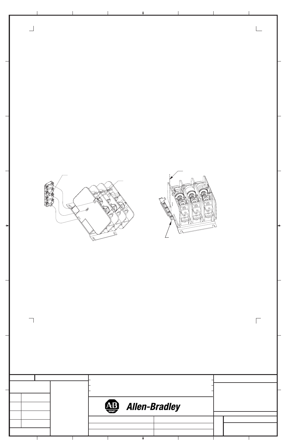
FIGURE 5A
FIGURE 5B
Vacuum Interrupter Phase Assembly Replacement Instructions
1. Disconnect all power cables (or bus work) and all control wiring to the contactor.
2. Remove the contactor from its mounted location. The contactor is best serviced in the tabletop position.
3. Remove the cover attachment screws from the contactor and remove the cover (Figure 3A) page 2.
4. Remove the Control-Pak from the contactor and set on benchtop (Figure 3B) page 2.
5. Locate the replacement vacuum interrupter phase assembly that needs to be replaced.
6. For the outer interrupters, remove the Retainer. Remove the screw from the line side terminal (Figure 6A).
7. Remove the screw from the load side terminal. This will free the shunt. Note the position of the shunt prior to removing the
interrupter assembly. Carefully remove the interrupter assembly
(Figure 6B).
(4)
1195C Auxiliary
Contact Actuator
Retainer
Auxiliary
Thin rod or
flat blade