Wiring – Rockwell Automation 1336S NEMA 4/12 Enclosure Kit User Manual
Page 2
2
1336 PLUS and PLUS II IP 65/54 (NEMA Type 4/12) Enclosure Kit
To install the drive, follow these steps:
1. Place the gasket, with the gasket paper still intact, around the
cutout area on the inside of the enclosure. Assure that the
mounting holes are aligned properly (mounting holes are not
equally spaced).
2. Peel away the gasket paper.
3. Firmly press the gasket in place aligning with the enclosure holes.
4. Remove the screws holding the drive mounting rails to the drive
back panel.
5. Install the drive in the enclosure using the mounting screws
provided with the kit.
6. Torque all mounting screws to 2.9 N-m (26 lb.-in.).
7. Connect the fan wires (A4 Frames & Up) as shown in the next
section.
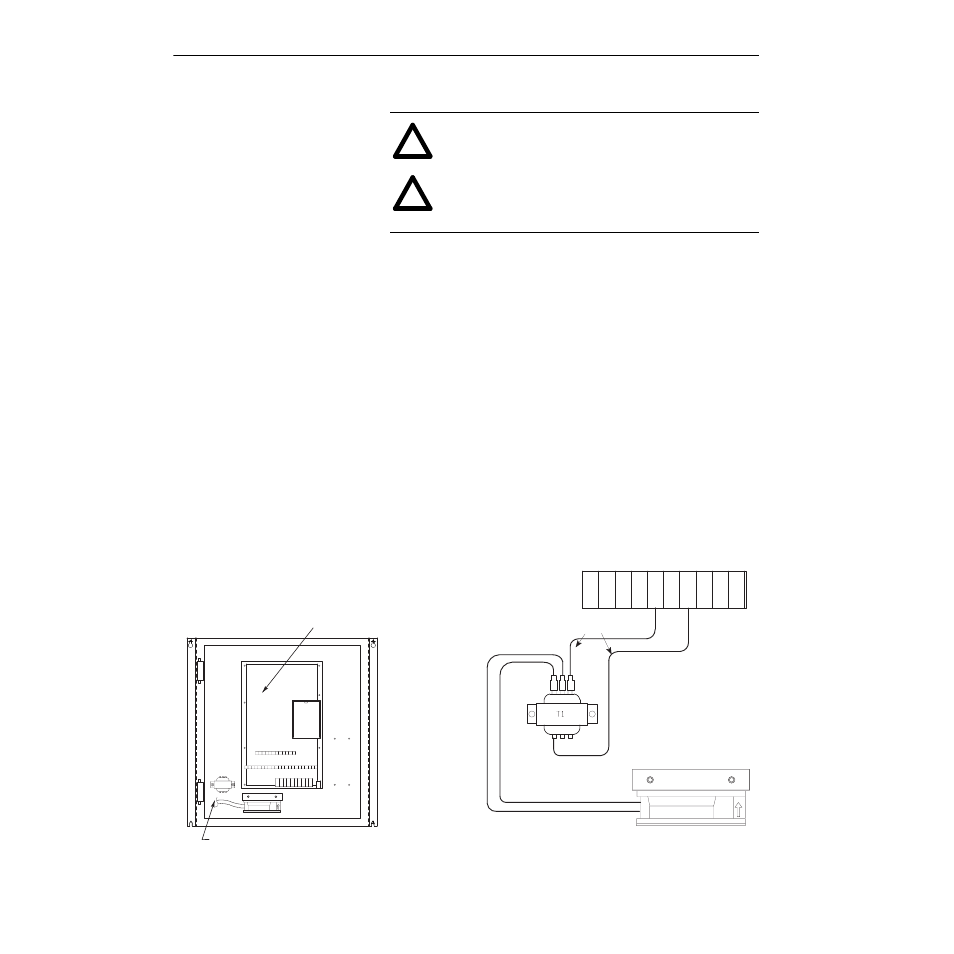
Wiring
The following diagram shows the typical wiring diagram for all
frames. Note that a fan is not required on A1-A3 frames.
!
ATTENTION: Electric shock can cause injury or death.
Disconnect all power before working on this product.
!
ATTENTION: Drive heatsink surface temperature may be
at or near 100 degrees C (212 degrees F). To avoid burns,
do not make contact with the drive heatsink.
Typical Inside View
Typical Wire Connections
(460V Connections Shown)
Fan
Typical Transformer/Fan Location
Pre-assembled Wires (Furnished)
Typical Drive Location
0V
380V
415V
115V
0V
460V
Fan
T1
19
TB3
TB2
TB1
20 21 22 23 24 25 26 27 28 29 30
TETE 1
1
2
2
3 4 5 6 7
P
E
P
E
D
C
+
D
C
–
J
2
R S T U V W
TB1
P
E
P
E
D
C
+
D
C
–
R S T U V W
8 9 10 11 12 13 14 15 16 17 18 A1 A2