Installing your 1394 ground clamps – Rockwell Automation 1394C-GCLAMP Ground Clamp Kit Installation Instructions User Manual
Page 2
2
1394 Ground Clamp Kit
Publication 1394-5.18 May 2000
Installing Your 1394 Ground
Clamps
The 1394 ground clamp kit is designed for use with 1394C-SJTxx-x
(Series C) system modules and 1394C-AMxx (Series C) axis modules
only.
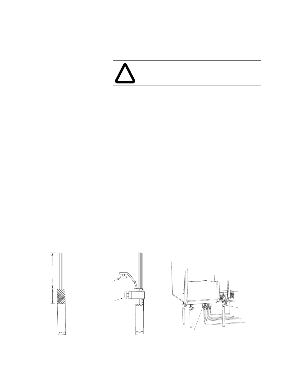
To install your system or axis module ground clamp:
1. Prepare one end of the cable for attachment to the cable shield
clamp by removing the outer insulation and braided shield from
the cable. Ensure approximately 51 mm (2.0 in.) of the insulated
cable wires are exposed (refer to Figure 1).
2. Remove another 22 mm (.875 in.) of insulation to expose the
braided shield underneath for clamp attachment.
Important: When cutting into the insulation use care not to cut
into the braided shield underneath.
3. Position the cable shield clamp over the exposed braided shield
(ensure clamp screw is behind clamp and not braided shield).
4. Tighten the clamp screw.
Important: Do not overtighten the clamp screw or damage to
the braided shield may result.
5. Thread the bracket screw into the bottom of the module and
tighten.
Figure 1
Series C Ground Clamp Installation
!
ATTENTION: To avoid a shock hazard, ensure that all
power to the system is removed before installing the
ground clamps.
1394 front view
System module
ground bar
Motor
feedback
cable clamps
Cable Preparation
Clamp Attachment
Wiring to System and Axis Module
Cable wires
Braided
shield
exposed
Cable
shield
clamp
Motor
feedback
or power
cable
Clamp
screw
Bracket
screw
Motor power
cable clamp
51 mm
(2.0 in.)
1
22 mm
(.875 in.)
1
Dimensions given are approximate and will vary
depending on the specific installation. Keep wires
as short as possible while maintaining adequate
stress relief.
1