Rockwell Automation 873P Analog or Discrete Ultrasonic Sensors User Manual
Page 3
3
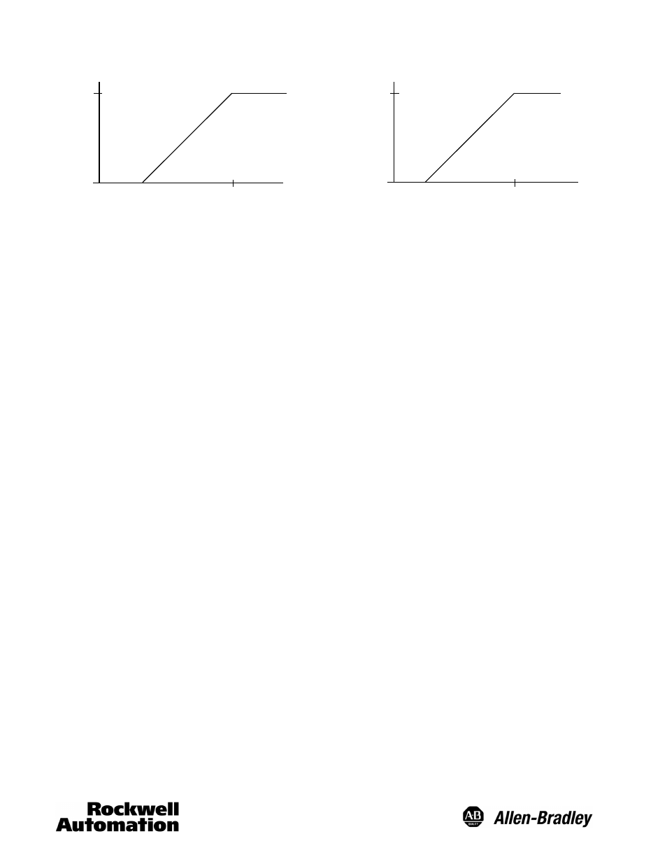
Analog Output
Analo
g
Cu
rr
en
t(
mA)
Anal
og
Vo
ltage
(V
DC)
Target Position—mm
20
100
600
200
1500
300
2500
Target Position—mm
0
10
100
600
200
1500
300
2500
4
Operation Principle
Ultrasonic sensors utilize a transducer that emits bursts of
high frequency sound waves in a cone shaped beam
pattern. These pulses are reflected or “echoed” from the
target back to the sensor and detected by the transducer.
The device determines the distance from the sensor to the
target by measuring the length of time for this echo to
return. Discrete models compare this duration to that of the
far limit which can be set by adjusting the potentiometer.
The output of the sensor is switched if the echo is returned
within this timeframe. The analog models convert the time
value to a DC current or voltage depending on the model.
There is an unusable area or deadband directly in front of
the sensor since there is a necessary time interval between
transmission and detection of the soundwave by the
transducer. This is the minimum distance at which the
target can be detected.
Sensing Distance
Bulletin 873P analog and discrete ultrasonic sensors are
available in three sensing ranges: 100--600mm,
200--1500mm, 300--2500mm. The sensing ranges are
determined using an industry standard 100mm X 100mm
flat steel target.
Target Considerations
Since the actual sensing distance to an object depends on
a reflected sound wave, target material, shape, size,
temperature, and position will influence operation; it is
possible that the sensing distance can be reduced or the
target may not be detected based on these characteristics.
The ideal target is a smooth, flat surface. Target material
that is not relatively sound reflective (fabric, foam rubber,
etc.) may be difficult to detect depending on the application.
Rounded or uneven objects can also be detected, but the
sensing distance may be reduced. For best performance,
the sensor should be aligned such that the sensor face is
parallel to the target surface.
Environmental Factors
The velocity of sound in air is dependent upon temperature
(sound waves travel faster at higher temperatures). Bulletin
873P ultrasonic sensors have internal temperature
compensation to adjust the ultrasonic frequency to
compensate for these changes in the ambient air
temperature. However, while this feature does compensate
for ambient temperature changes, temperature variations
within the sensing range due to convection currents,
heating/cooling elements, etc., may still divert or refract the
sound wave and adversely affect sensor performance.
Strong air turbulence can also influence the signal and
adversely affect the stability and overall sensor operation.
Humidity does not significantly affect ultrasonic sensor
operation, but changes in humidity can have a slight affect
in some instances due to the absorption of sound.
Mounting Considerations
The sensor must be securely mounted on a firm stable
surface or support. A mounting configuration that is
unstable or subject to excessive vibration may cause
intermittent operation.
A mounting location should be chosen such that the sensor
faces directly toward the target’s surface (perpendicular to
the barrel axis of the sensor).
When using more than one 873P there is a potential for
cross-talk (mutual interference) between the sensors. As a
result, consideration should be given to the spacing
between the sensors. See the beam pattern chart for the
minimum acceptable distance between sensors that are
mounted side by side. When the sensors must be mounted
facing each other they should be separated by a distance at
least 4 times the maximum sensing range for the model.
If the sensors must be mounted close together due to
application requirements, the Hold or Synchronize
functions can be used to reduce cross-talk.
The Hold function stops the sensor from transmitting and
receiving ultrasonic pulses, which eliminates the potential
for cross-talk. This function also can be used to hold the
output to its existing state or value. For details see the Hold
function in the Wiring/Control Pin section.