Dimensions wiring diagrams, Control pin, Beam pattern – Rockwell Automation 873P Analog or Discrete Ultrasonic Sensors User Manual
Page 2
2
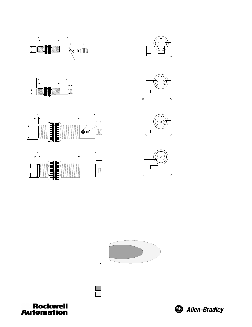
Dimensions
Wiring Diagrams
18mm Discrete
92 (3.62)
300
(11.8)
65 (2.55)
M18 x 1
Output LED
--
+
2 1
3 4
--
+
18--30V DC
Load
Adjustment
Potentiometer
Control
(Hold/Synchronize)
18mm Analog
Control
(Hold/Synchronize)
90 (3.54)
14
(0.55)
65 (2.55)
M18 x 1
--
+
2 1
3 4
--
+
18--30V DC
Load
4--20mA
0--10V DC
30mm Discrete
125 (4.92)
90 (3.54)
12
(0.47)
M30 x 1.5
5
(0.19)
Adjustment
Potentiometer
Output LED
--
+
2
1
3 4
--
+
18--30V DC
Load
5
Control
(Hold/Synchronize)
30mm Analog
4--20mA
0--10V DC
M30 x 1.5
125 (4.92)
90 (3.54)
12
(0.47)
5
(0.19
)
--
+
2
1
3 4
--
+
18--30V DC
Load
5
Control
(Hold/Synchronize)
Control Pin
Normal Operation
For normal operation do not connect the control pin. Hold
and synchronize features can be used for special
applications.
Hold
To inhibit sensor operation and hold the output to its present
state connect the control pin (2) to 0V DC. The sensor will
not transmit or receive ultrasonic pulses until this voltage is
removed from the control pin. Switching output models will
be latched and analog output models will hold their value
during this period.
Synchronize
To synchronize the transmission of ultrasonic pulses
between several sensors connect the control pins together.
This feature reduces the potential for sensor crosstalk
between models that are mounted in close proximity to one
another.
Beam Pattern
300
Distance—mm
150
100
300
150
100
0
100
600
200
1500
300
2500
W
idt
h—
mm
Assured detection of 100mm x 100mm target
Possible detection of a large target