Rockwell Automation 1492 Modicon 800-to-1756 I/O Swing-arm Conversion System User Manual
Page 6
(6)
10000021923 (Version 00)
II. Conversion Steps
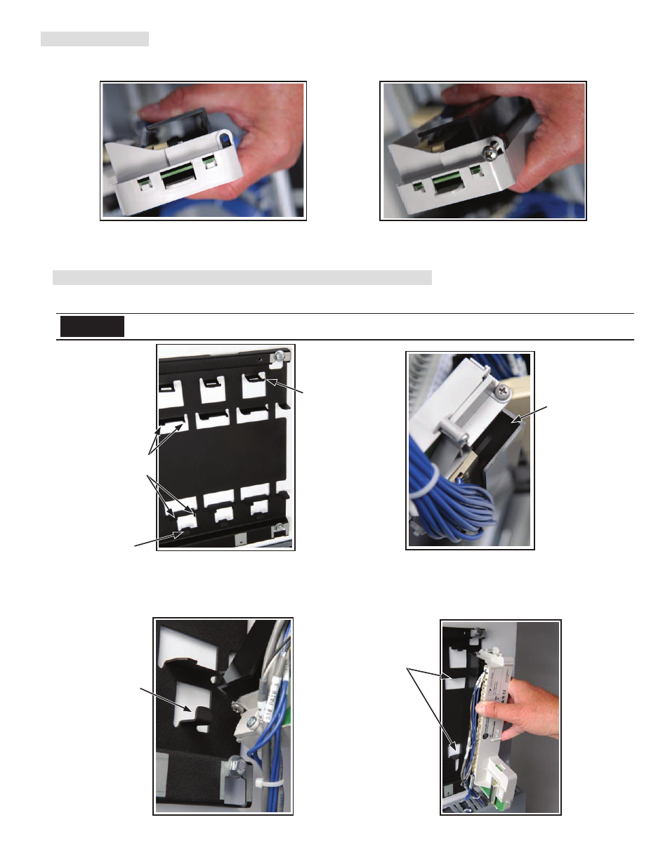
e) Refer to Figures 4g and 4h. Use the upper and lower #10-32 x 1 inch phillips mounting screws you saved in Step 1b, attach the terminal block to
the conversion module. Torque to 10 lb-in.
f) Gently place the completed conversion module and terminal block assembly below the conversion system base-plate. Repeat steps a through e
above for all of the remaining terminal block conversions associated with this I/O housing.
5) Install the Conversion Module/Terminal Block Assemblies into the Base-Plate
Begin installing conversion module/terminal block assemblies into the conversion base-plate starting with the right most base-plate
slot used in your configuration.
a) Refer to Figures 5a through 5d. Refer to the opening at the bottom of the assembly and the hook/mounting tab at the bottom of the base-plate.
Also notice the horizontal module guides on the base-plate. Guide the lower part of the conversion module/terminal block assembly into the lower
hook/mounting tab of the base-plate. This works best if the module approaches the base-plate at approximately a 60 degree angle from the back
of the base-plate.
Figure 5d
Figure 5c
Figure 5b
Figure 5a
Figure 4h
Figure 4g
Align module to
upper and lower
guides and snap
into base plate
Insert module
opening on to the
base plate lower
hook / mounting
tab
Opening in the
lower part of the
conversion module
/ terminal block
assembly
Spring locking tab
Upper and lower
horizontal module
guides
Lower hook /
mounting tab
The slot locations of the base-plate should match those used in the previously installed Modicon I/O housing. Refer to wiring
schematics to confirm the correct location.
NOTICE
NOTICE