Quick installation guide, Cutting connecting rod, Disconnect switc h hole location template (600a) – Rockwell Automation 1494V-DS600 - Series D Variable Depth Disconnect Switch Kit and Accessories (600A) User Manual
Page 2: Use opposite side f or left hand installation), Tape
A
HOLD FLUSH
TO
INSIDE
OF ENCLOSURE
MEASURE T
O
INSIDE OF
THE
TOP OF ENCLOSURE
TOP
BO
TT
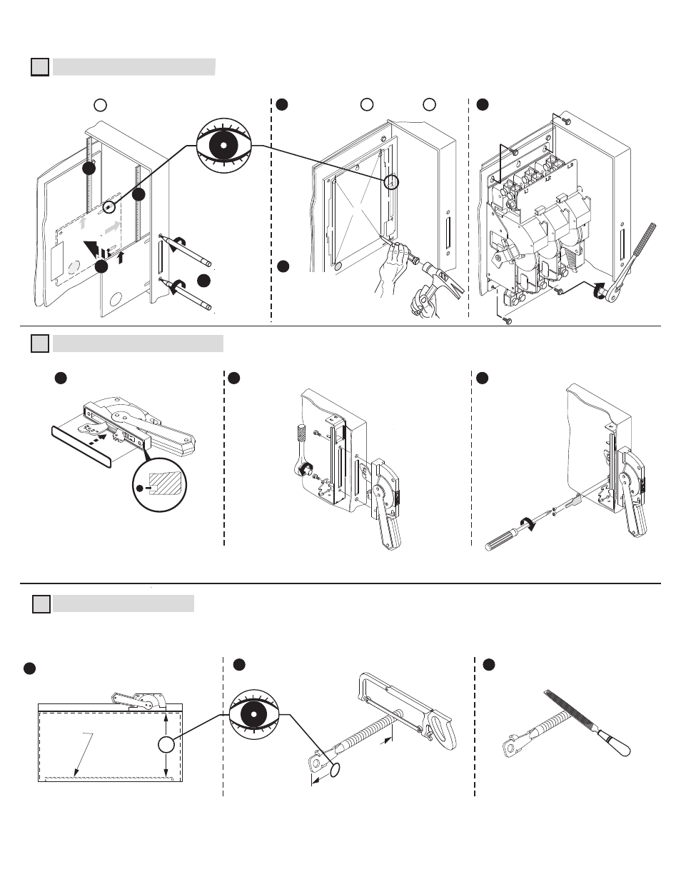
Disconnect Handle Installation
Disconnect Switch Installation (Right hand installation shown. For left hand installation follow similar procedure.)
1
2
Install gasket.
60-80 lb-in
Install handle and spring bracket.
Use template D to locate handle holes on mounting plate.
Overlay template F (600 A) over D .
Install defeater lever.
Cutting Connecting Rod
(Cut (2) Connecting Rods; first rod connects the handle to the switch, second rod provides
stiffening for the enclosure flange)
N
N minus 3-3/4"
Enclosure
Working Depth
(Inside Flange
of Enclosure to
Mounting Plate)
Mounting
Plate
Measure working depth of enclosure.
3
Measure, mark and
cut (2) connecting rods.
5
1
1
2
Remove burrs.
3
2
3
Install disconnect switch.
7
IMPORTANT:
Apply grease to O-Ring
to retain into handle groove.
7-11 lb-in
6
D
HOLD FLUSH
TO
INSIDE
OF ENCLOSURE
MEASURE T
O
INSIDE OF
THE
TOP OF ENCLOSURE
TOP HANDLE H
OLE
BO
TT
OM HANDL
E HOLE
TAPE
HOLD FLUSH
TO
INSIDE
OF ENCLOSURE
MEASURE T
O
INSIDE OF
THE
TOP OF ENCLOSURE
TOP
BO
TT
D
1
1
3
2
4
90 -130 lb-in
8-1/4"
4-1/8"
6-5/8"
15"
2-
1/16"
6-1/2"
420
52
-1
85-01 (
1)
Pr
int
ed
in
U
.S.
A.
F
Disconnect Switc
h Hole Location
Template (600A)
RIGHT
Hand Installation
(Use opposite side f
or left hand installation)
Switc
h Mounting Holes
Center p
unc
h and drill (4) 9/32" holes f
or #5/16-18 thread
forming (T
AP-TITE) scre
ws pr
ovided with s
witc
h
Center punch
and drill (4) holes
for 5/16-18 thread forming
screws provided with switch.
9/32" Dia.
QUICK INSTALLATION GUIDE
(2)
42052-183-01
DIR 42052-183 (Version 03)