Installation, Continued), Side – Rockwell Automation 1397 NEMA Type 1 Brake Installation Inst. User Manual
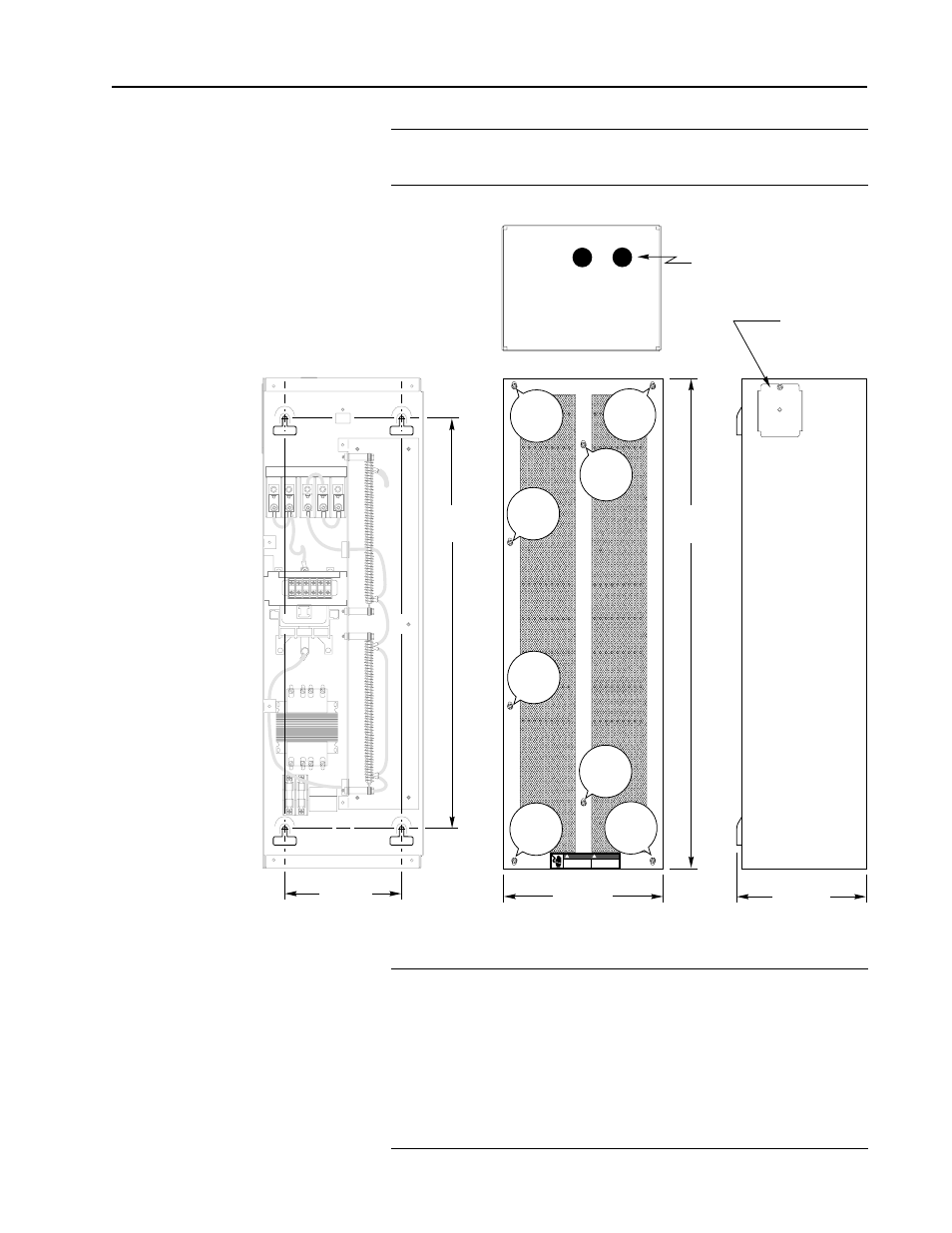
Page 3: Front, Cover removed
1397 NEMA Type 1 Dynamic Brake
3
1397-5.14 March, 1997
❐
1
Remove and lockout all incoming power to the drive. Remove
the (8) cover screws to remove the brake cover.
Installation
(continued)
SIDE
194.4mm
(7.65 In.)
TOP
DANGER
810293-200A
DISCONNECT INPUT POWER
BEFORE SERVICING EQUIPMENT.
FAILURE TO OBSERVE THESE
PRECAUTIONS COULD RESULT
IN SEVERE BOCILY INJURY OR
LOSS OF LIFE.
!
DANGER
COUPER L'ALIMENTATION AVANT
LA MAINTENANCE. SI CES
PRECAUTIONS NE SONT PAS
PRISES, ON RISQUE DES
BLESSURES GRAVES OU MORTELLES.
!
`
DGI
FRONT
246.0mm
(9.69 In.)
755.3mm
(29.74 In.)
246.0mm
(9.69 In.)
755.3mm
(29.74 In.)
A1
S2
A1
45
A2
S1
1 2 3 4 5 6
GRD
REPLACE FUSES
WITH
16FU 17FU
LITTLEFUSE
type KLDR
600V .6A
COVER REMOVED
27.94mm (1.1 IN.) DIA. CONDUIT HOLES
— (2) PLACES —
88.9mm
×
88.9mm
(3.5 IN.
×
3.5 IN.)
REMOVABLE
CONDUIT PLATE
Cover
Screw
Cover
Screw
Cover
Screw
Cover
Screw
Cover
Screw
Cover
Screw
Cover
Screw
Cover
Screw
❐
2
Included with the Dynamic Brake kit is a 1.22m (48 In.)
interconnection cable to supply AC power between the drive’s
fuses and the Dynamic Brakes’ control transformer. The
Dynamic Brake is mounted using (4) user supplied mounting
fasteners (6mm fasteners is recommended). Leave a minimum
of 0.20 In. (5mm) space between the head of the screw and the
mounting panel to slide the brake assembly over the heads of the
fasteners.