Original instructions – Rockwell Automation 440L GuardShield Type 2 Safety Light Curtain User Manual User Manual
Page 9
R
GuardShield™ Type 2 Safety Light Curtain Installation Instructions
7
Original instructions
• Resolution of the light curtain and/or beam separation.
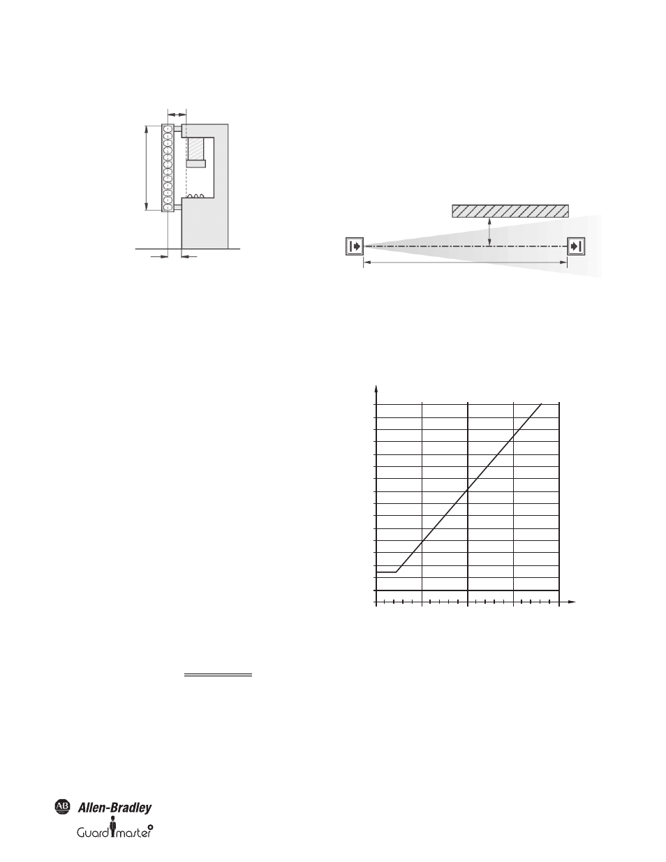
Figure 2: Safety distance from the point of danger
How to Calculate the Safety Distance S
According to EN ISO 13855 and EN ISO 13857:
→ First, calculate S using the following formula:
S = 2000 × T + 8 × (d – 14) [mm]
Where …
T = stopping/run-down time of the machine
+ response time of the protective device [s]
d = resolution of the light curtain [mm]
S = safety distance [mm]
The reach/approach speed is already included in the formula.
→ If the result S is ≤ 500 mm (19.6 in.), then use the
determined value as the safety distance.
→ If the result S is > 500 mm (19.6 in.), then recalculate S as
follows:
S = 1600 × T + 8 × (d – 14) [mm]
→ If the new value S is > 500 mm (19.6 in.), then use the newly
determined value as the minimum safety distance.
→ If the new value S is ≤ 500 mm (19.6 in.), then use 500 mm
(19.6 in.) as the safety distance.
Example:
Stopping/run-down time of the machine = 290 ms
Response time = 30 ms
Resolution of the light curtain = 30 mm (1.18 in.)
T = 290 ms + 30 ms = 320 ms = 0.32 s
S = 2000 Ч 0.32 + 8 Ч (30 – 14) = 768 mm (30.24 in.)
S > 500 mm, therefore:
S = 1600 Ч 0.32 + 8 Ч (30 – 14) = 640 mm (25.1 in.)
Example:
In opto-electronic safeguarding, such as with a perpendicular safety light
curtain applications with object sensitivity (effective resolution) less than
2.5 inches, the D
pf
can be approximated based on the following formula:
D
pf
(inches) =3.4 × (Object Sensitivity – 0.276),
but not less than 0.
Minimum Distance from Reflecting Surfaces
The infrared light from the sender may be reflected off of shiny surfaces
and be received by the system’s receiver. If this condition occurs, it can
result in an object not being detected when it enters the GuardShield
Type 2 sensing field.
All reflecting surfaces and objects (e.g. material bins) must therefore be
located at a minimum distance
a from the protective field of the system.
The minimum distance
a depends on the distance D between sender and
receiver.
Figure 3: Minimum distance from reflecting surfaces
How to Determine the Minimum Distance from the
Reflecting Surfaces:
→ Determine the distance D [m] sender-receiver
→ Read the minimum distance a [mm] from the graph:
Figure 4: Graph, minimum distance from reflecting surfaces
Safety distance S (D
s
)
Protective field height
Point
Distance to avoid standing behind
of
danger
the safety curtain
≤75mm
a
Distance D (meters)
1600
1500
5
15
20
3
10
a (mm)
800
100
900
300
1000
200
1100
400
1200
500
1300
600
1400
700
D (m)