Dr. date, Sheet size ver of 2 2 – Rockwell Automation 800HL-EMP Selector Switches User Manual
Page 2
Enclosure must comply with U.L. standards 698 and 1203 and CSA standard C22.2 No. 30 for Class I
Groups B, C and D hazardous locations or C22.2 No. 25 for Class II Groups E, F and G hazardous
locations. For Class I locations, a suitable seal fitting is required within 18 inches.
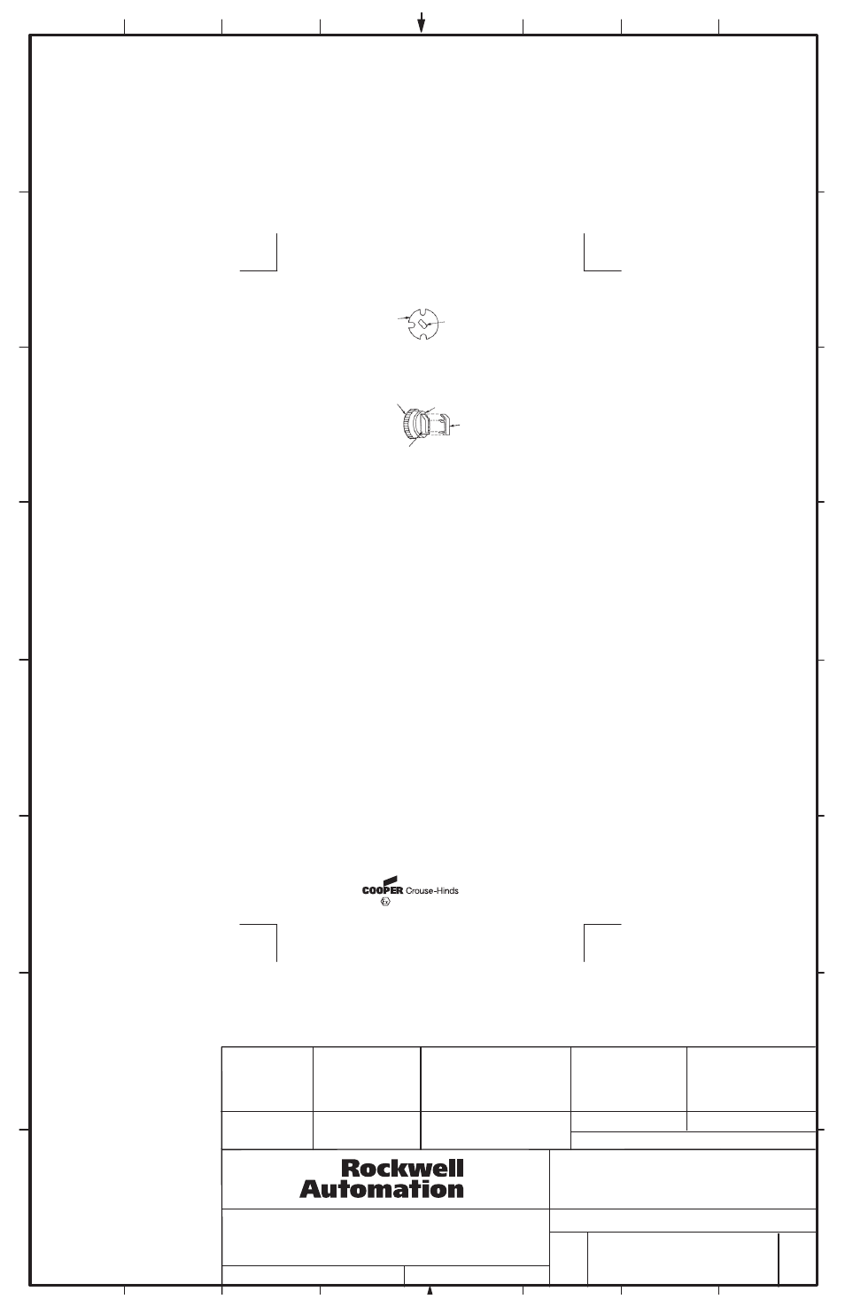
Hole size to be .958 (24.30) to .970 diameter (24.60) ¾-14NPSM tap.
Apply grease from capsule (supplied) to threads of ¾-14NPSM hole before assembling units into panel
and to the threads of the lens assembly.
Maximum panel thickness is 2-1/2" (63.5). For panels above 2" (50.8) but not exceeding 2-1/2" (63.5)
remove and discard securing ring and tighten device with adjusting nut only.
For Class I Group B application, 5/8" (15.9) minimum panel thickness is required.
Knobs have replaceable color inserts. To remove place sharp instrument under insert at the mounting ring
and pry up. Grasp insert and remove from operator. To install new insert, place into slot in operator and
apply light pressure to assure seating place (see Figure 4).
MOUNTING
RING
KNOB
ASSEMBLY
SHAFT PLATE
RIVET
KNOB
Figure 4
Figure 3
PRY UP HERE
INSERT
B-vertical.ai
1
2
3
4
5
6
7
8
A
B
C
D
E
F
G
H
CONFIDENTIAL AND PROPRIETARY INFORMATION. THIS DOCUMENT
CONTAINS CONFIDENTIAL AND PROPRIETARY INFORMATION OF
ROCKWELL AUTOMATION, INC. AND MAY NOT BE USED, COPIED OR
DISCLOSED TO OTHERS, EXCEPT WITH THE AUTHORIZED WRITTEN
PERMISSION OF ROCKWELL AUTOMATION, INC.
800HL-EMP SELECTOR SWITCH
INSTALLATION
INSTRUCTION SHEET
10000008895
Sheet
Size
Ver
Of
2
2
B
01
Dr.
Date
- - - - - -
- - - - - -
MATERIAL
NO.
MATERIAL
SIZE
FOLD
FLAT
4" W x 8-1/2" H
4" W x 2-1/8" H
TWO SIDES PRINTED
BODY STOCK WHITE
BODY INK BLACK
PN-25582
PN-14270
SUPERSEDES
SYRACUSE, NY 13221 USA
0359
II 2 G EEx d IIB + Hydrogen ITS07ATEX15664U
PN-25582
DIR 10000008895
(Version 01)
Printed in U.S.A.
PANEL
� �
ADJUSTING NUT
SECURING RING
�
�