Rockwell Automation 800HL-EMP Selector Switches User Manual
Sheet size ver of 2 1
INSTALLATION INSTRUCTIONS
800HL-EMP SELECTOR SWITCHES
FOR NEMA TYPE 7 [3/8" (9.5) TO 2-1/2" (50.8)
PANELS] AND TYPE 9 [7/32" (7.2) TO 2-1/2" (50.8) PANELS]
�
(Dimensions shown in parentheses are in millimeters)
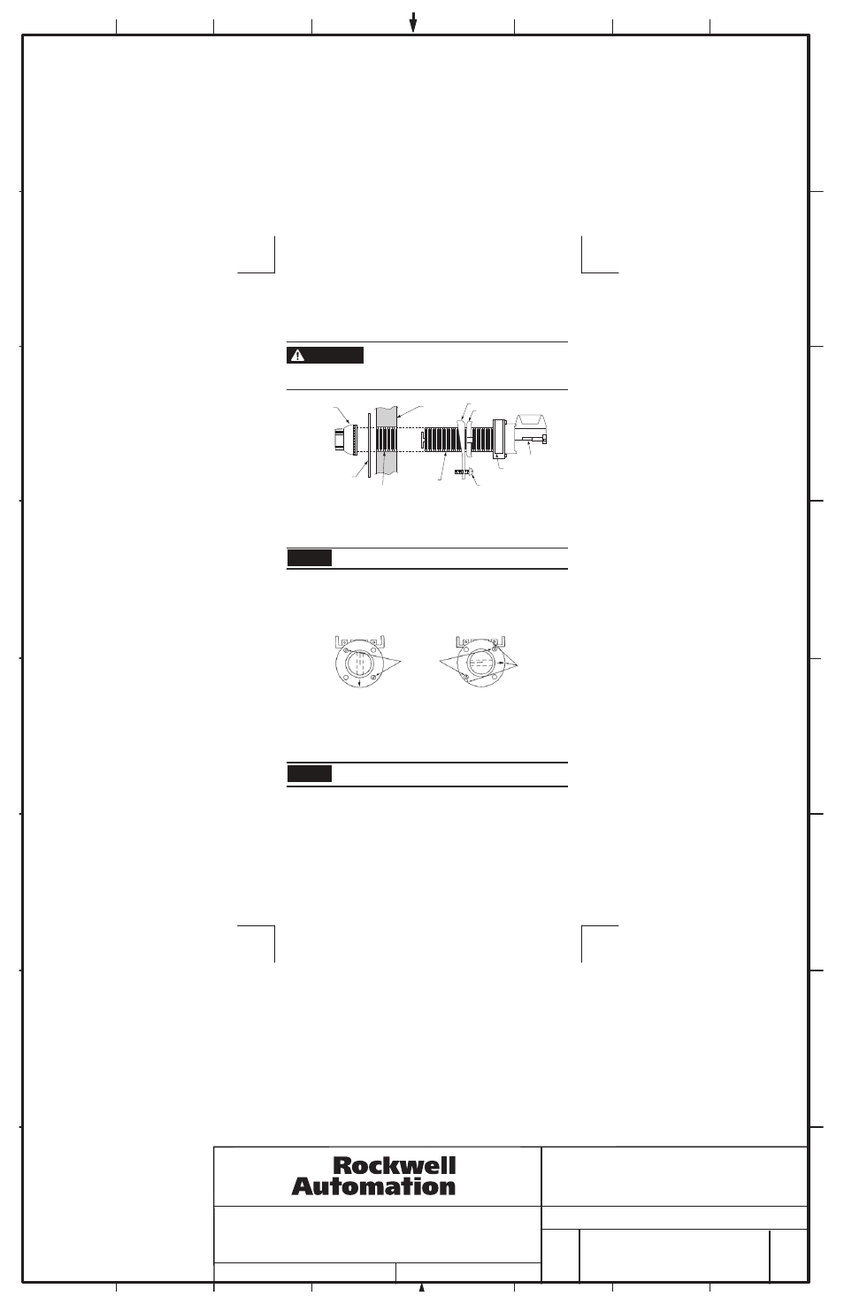
Installation: See Figure 1 for illustrated assembly
1. Place securing ring and/or adjusting nut as supplied on unit as shown above and thread unit into
panel until bushing extends approximately 9/32" (7.1) [3 to 4 threads] past front of panel. 7/32" (5.6)
[2 to 3 threads] if a legend plate is not to be used.
The specified extension of the bushing is necessary to provide engagement of the operating knob.
2. To secure unit, rotate to assure electrical clearance and tighten adjusting nut and/or locking screw
securely. Where two units are mounted adjacent to each other, arrange securing rings to avoid
interference.
3. Place legend plate, if used, over mounting bushing.
NOTE: Remove knob, lever or key before modification.
1. With a felt pen or crayon, make reference marks on the mounting bushing to identify the side
adjacent to the nameplate and the holes in which the flat-head screws are assembled.
2. Remove the two flat-head screws and lift the mounting bushing straight off of the base. Do not twist.
Do not rotate any parts within either the base assembly or the mounting bushing while these two
subassemblies are separated from each other, as this can cause incorrect switch operation after
reassembly.
3. 2 and 3 position selector switches: While separated from the base, turn the mounting bushing
counterclockwise 90° and reassemble the unit.
4 position selector switches: While separated from the base, turn the mounting bushing clockwise
90° and reassemble the unit.
NOTE: In the proper position originally - used mounting screw holes will be aligned with tapped holes in
the base.
4. Reassemble and torque the two flat-head screws to 8 ± 1 lb.-in.
5. Check the switch for proper operation and correct contact action.
To assemble the operating knob, align the colored insert with the rivet of the shaft plate (see Figure 3).
Tighten the knob assembly onto the mounting bushing. Knob assembly should clamp legend plate
tightly when properly assembled.
FLAT HEAD
SCREWS
Device For Vertical Mounting
Front View
Device For Horizontal Mounting
Front View
REFERENCE MARKS
LEGEND PLATE
MOUNTING
BUSHING
LOCKING SCREW
NAMEPLATE
CONTACT BLOCK
STANDARD
KNOB
Figure 1
Figure 2
B-vertical.ai
1
2
3
4
5
6
7
8
CONFIDENTIAL AND PROPRIETARY INFORMATION. THIS DOCUMENT
CONTAINS CONFIDENTIAL AND PROPRIETARY INFORMATION OF
ROCKWELL AUTOMATION, INC. AND MAY NOT BE USED, COPIED OR
DISCLOSED TO OTHERS, EXCEPT WITH THE AUTHORIZED WRITTEN
PERMISSION OF ROCKWELL AUTOMATION, INC.
800HL-EMP SELECTOR SWITCH
INSTALLATION
INSTRUCTION SHEET
10000008895
Sheet
Size
Ver
Of
2
1
B
01
Dr.
Date
G. Ushakow
06-08-08
To avoid damage to equipment or injury to personnel, electrical
power must be off before and during installation and maintenance.
Maintain ½" (12.7) minimum clearance through air between
current-carrying parts and enclosure.
WARNING
NOTICE
NOTICE
PANEL
� �
ADJUSTING NUT
SECURING RING
�
�