Caution – Rockwell Automation 140U Q, M Frame CB Installation and Operation for Thermal Magnetic Trip Units User Manual
Page 3
40752-077(2)
Effective 5/02
Page 3
DO NOT EXCEED SPECIFIED TORQUE. EXCESSIVE
TORQUING WILL SHEAR SCREWS.
FAILURE TO APPLY THE REQUIRED TORQUE MAY
LEAD TO EXCESSIVE HEATING AND CAUSE
NUISANCE TRIPPING OF THE CIRCUIT BREAKER.
2-5.
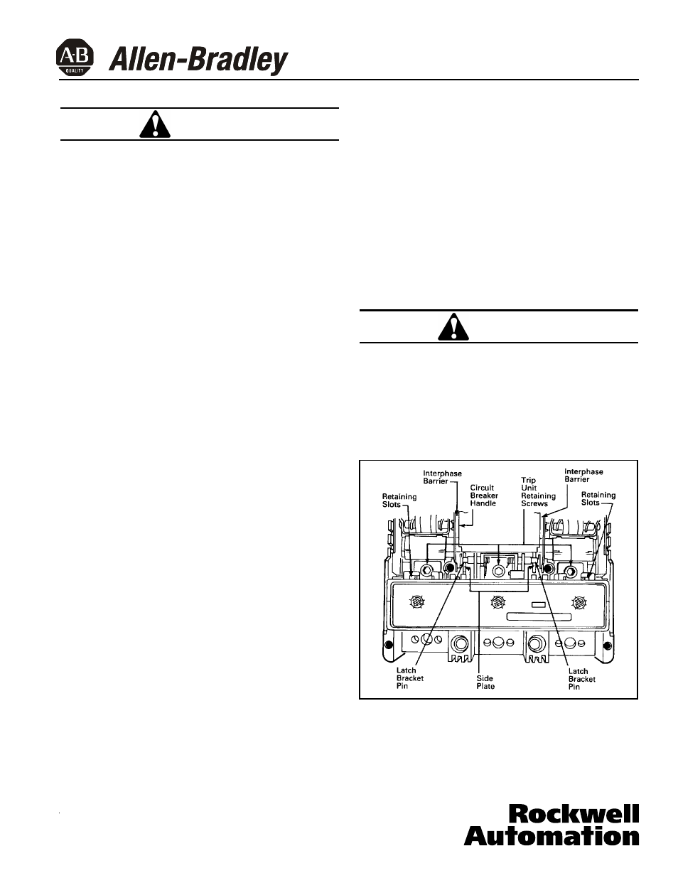
Screw in and tighten the trip unit retaining screws in
each pole (mechanism pole first). Torque the line-
end screws to 10-12 Ib ft (13.56-16.27 N.m) (See
Fig. 2-1). For the M-frame, torque the load-end
screws to 6-8 lb ft (8.14-10.85 N.m). (See Fig. 2-2.)
2-6.
Install accessory(ies), if required. For poles where
accessories are not required, install protective bar-
riers supplied with trip unit in accessory retaining
slots.
2-7.
Make sure interphase barriers are in slots in the
base of the circuit breaker.
2-8.
Make sure that opening in sliding handle barrier
(captive in cover) is aligned with circuit breaker
handle.
Note: Circuit breaker cover can be installed or
removed only if the circuit breaker is in the
“TRIPPED” or “OFF” position.
2-9.
Install the circuit breaker main cover and terminal
cover on the Q-Frame. Install the main cover and
both terminal covers on the M-Frame. Secure
with the original screws and torque them to 20-22
Ib in (2.26-2.49 N.m). (See Fig. 2-2.)
2-10. Reset circuit breaker by moving handle to the reset
position. Move handle to the ON position. Circuit
breaker should remain ON.
2-11. Press PUSH-TO-TRIP button with a small screw-
driver to check manual tripping of the circuit
breaker (see Fig. 2-3).
Trip Unit Magnetic Adjustment
The magnetic element of each pole of the trip unit can be
adjusted by rotating the adjustment buttons on the front
face of the trip unit with a screwdriver. The buttons have
several settings as indicated on the nameplate with val-
ues in multiples of the trip unit ampere rating (I
n
) as
shown in Fig. 2-3.
Note: Button must be set at detents and not at inter-
mediate positions.
To adjust the setting, rotate each button until arrow on
button points to desired setting.
2-12. Adjust magnetic pick-up settings as required (see
Fig. 2-3).
Trip Unit Thermal Adjustment
In some trip unit types, the thermal rating (I
n
) of the trip
unit can be adjusted by a single button (see Fig. 2-4)
within the ranges indicated in Table 1-2.
TO PREVENT POSSIBLE INTERNAL DAMAGE TO
THE TRIP UNIT, THE CIRCUIT BREAKER MUST BE
TRIPPED PRIOR TO CHANGING THE THERMAL
ADJUSTMENT.
2-13. Adjust thermal setting as required (see Fig. 2-4) by
rotating the thermal adjustment button until the
arrow on the button points to the desired setting.
Fig. 2-1 Trip Unit Installed in a Q-Frame
CAUTION
CAUTION