Wiring, Accessories – Rockwell Automation 871P VersaCube Proximity Sensor User Manual
Page 2
Copyright © 2012 Rockwell Automation, Inc. All Rights Reserved.
PN-172832
10000352894 ver 00
September 2012
Printed in USA
Power, Control and Information Solutions Headquarters
Americas: Rockwell Automation, 1201 South Second Street, Milwaukee, WI 53204-2496 USA, Tel: (1) 414.382.2000, Fax: (1) 414.382.4444
Europe/Middle East/Africa: Rockwell Automation NV, Pegasus Park, De Kleetlaan 12a, 1831 Diegem, Belgium, Tel: (32) 2 663 0600, Fax: (32) 2 663 0640
Asia Pacific: Rockwell Automation, Level 14, Core F, Cyberport 3, 100 Cyberport Road, Hong Kong, Tel: (852) 2887 4788, Fax: (852) 2508 1846
www.rockwel lautomation.com
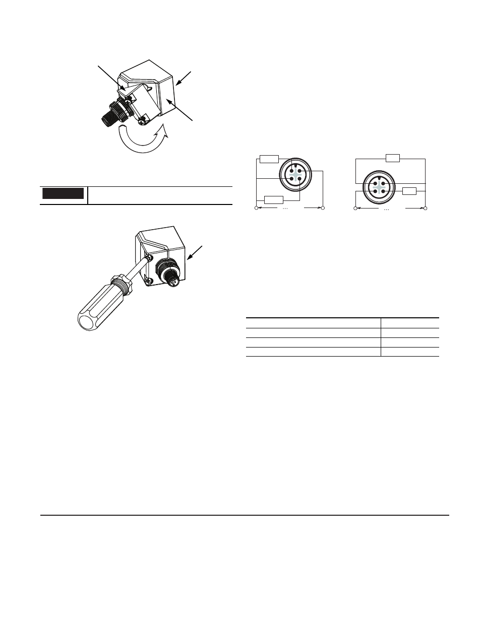
2. Unscrew the two 6-32 pan head screws. Note: Each screw
includes a captive internal-tooth lock washer.
3. Pull sensor head and 45-degree mounting base gently apart
and twist 180° to the new position.
4. Re-install the two 6-32 screws with washers, and torque to
0.56 N-m (5 in-lb), maximum.
Do not pull on the connecting cable or rotate more than 180°,
as damage to the sensor may result.
45-degree mounting base
Sensor head
Sensor face
IMPORTANT
Sensor face
Wiring
All external wiring should conform to the National Electric Code
and applicable local codes. Connect the proximity switch to the
power supply and load as shown in the wiring diagrams below. If
the positive (+) and negative (–) wires on the DC switches are
reversed, the switch will not operate properly.
Wiring Diagrams for DC switches, Micro Connector
Accessories
Accessory Description
Catalog Number
Zinc Mounting Bracket
871A-PBR
Stainless Steel L-Bracket (includes one 22 mm Plastic Mounting Nut) 871A-BRS59
22 mm Plastic Mounting Nut
871T-N9
--
+
Load
N.C.
+
--
Load
N.O. +
--
10 30V DC
1
3
2
4
--
+
Load
N.C. +
--
Load
N.O.
+
--
10 30V DC
1
3
2
4
Note: Class 2 source required
Complementary Normally Open and Normally Closed
NPN Sinking
PNP Sourcing